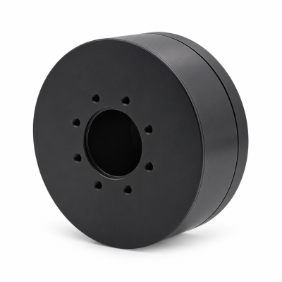
MG3505-8
 MG3505-9
 MG3505-36
 MG4315-8
 MG6010-6
 MG6010-8
 MG4305-10
 MG4310-10
 MG4310-36
 MG4310-40
 MG3510-8
 MG3510-64
 MG6010-36
 MG6010-48
 MG8108-6
 MG8108-8
 MG8108-36
 MG8108-48
 MG8115-6
 MG8115-9
 MG8115-36
 T-4024
 T-4929
 T-6034
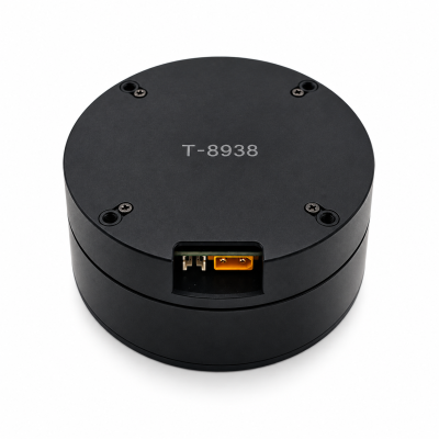
 T-8938
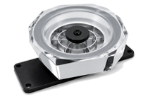
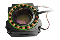
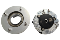
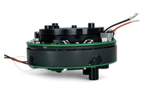
What Is a QDD Motor and Why Is It Used in Robots?
Direct answer. A QDD motor usually means a quasi-direct-drive actuator: a torque-producing motor paired with a low-ratio transmission. The reduction raises output torque while retaining some of the response and backdriving characteristics sought in direct drive. Robots use this approach when contact response matters, but the ratio alone cannot establish torque control quality, thermal capacity, impact tolerance or safety. Evaluate the complete joint.
For available hardware, start with the SolisMotor robot joint motor range. This guide explains what the QDD label tells you, what it leaves unspecified, and which evidence to request before choosing a joint.
What does quasi-direct drive mean?
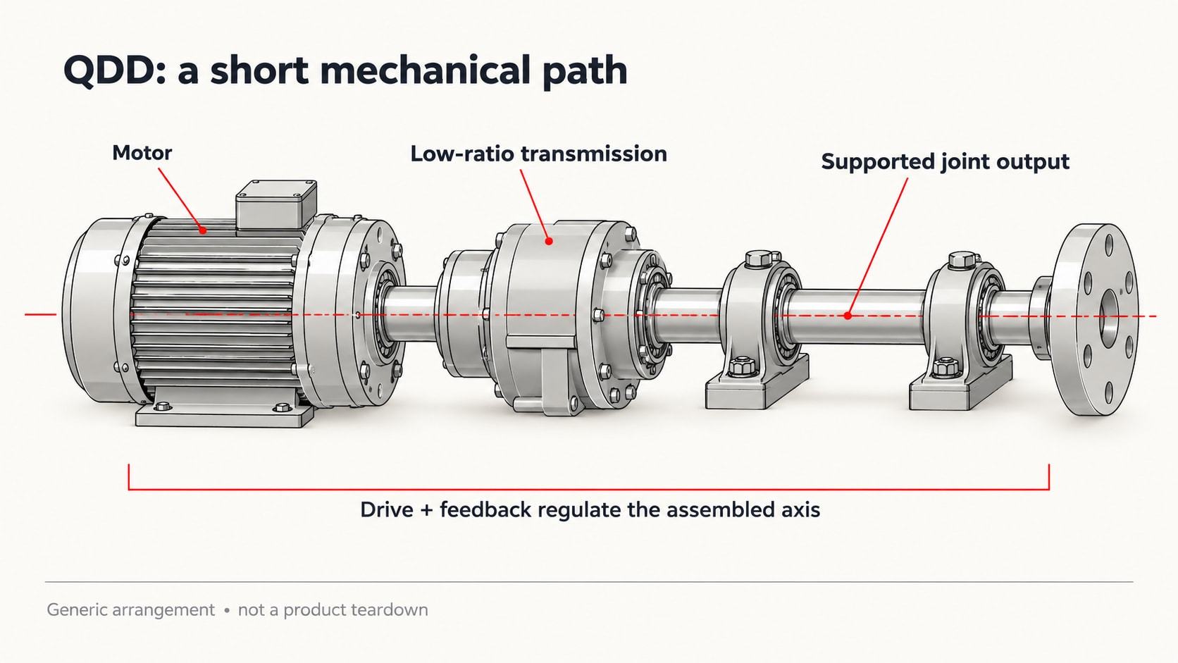
Direct drive couples the motor to its load without a reduction gearbox. QDD retains a relatively small reduction so that the motor can contribute useful joint torque without all of the reduction used in some higher-ratio designs. The complete assembly may also include bearings, feedback, a housing and drive electronics. “QDD motor” is convenient search language; QDD actuator is usually the more precise description of the assembly.
There is no single ratio cutoff established by the sources used here that qualifies every actuator as QDD. Research implementations use different motors and transmissions. Specify the actual ratio and mechanism rather than treating the abbreviation as a standard or certification. A planetary gearbox is one possible implementation; the term does not require every QDD design to use one.
How does the reduction change torque and speed?
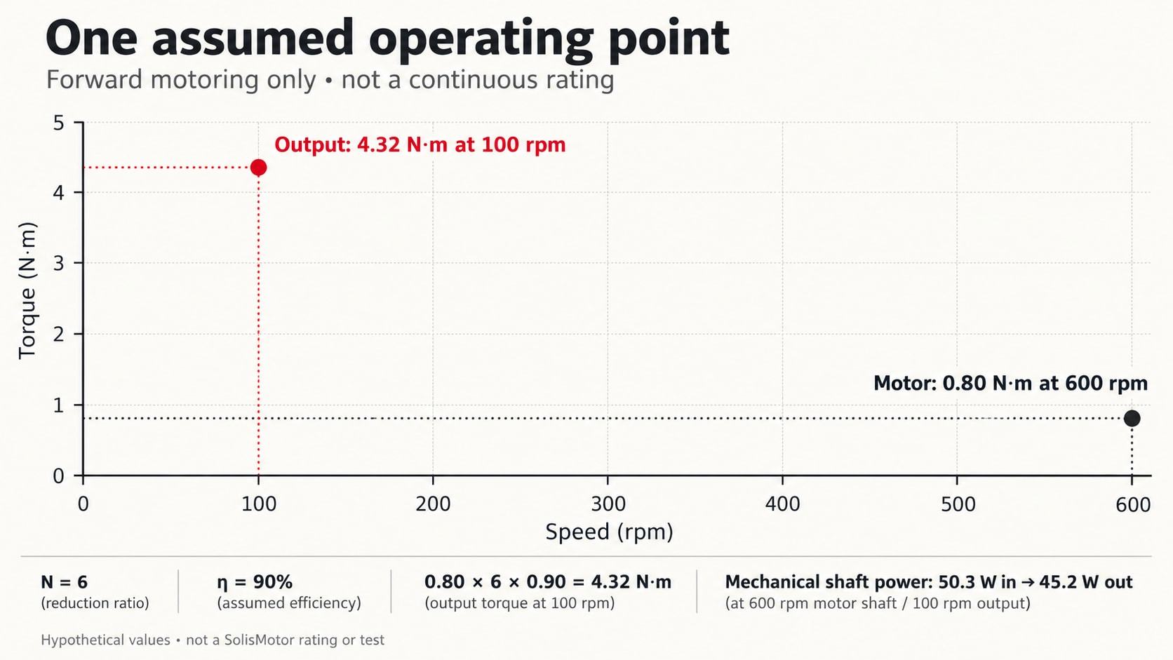
Define the reduction ratio as N = motor speed ÷ output speed. For forward motoring at a particular operating point, a first estimate is:
- Output speed ≈ motor speed ÷ N
- Output torque ≈ motor torque × N × transmission efficiency
The transmission trades speed for torque; it does not create power. These estimates do not describe every transient, reverse-driving condition or gearbox limit.
Hypothetical operating point—not a SolisMotor rating or test: assume motor torque of 0.80 N·m at 600 rpm, a 6:1 reduction, and 90% forward transmission efficiency at that point. Estimated output is 4.32 N·m at 100 rpm. Mechanical power falls from approximately 50.3 W at the motor shaft to 45.2 W at the output. This is one assumed operating point, not a continuous torque–speed envelope or an efficiency claim for an actual gearbox.
Why is QDD used in robots?
Engineers investigate low-ratio actuation for joints that need to respond to contact and changing loads. University research has explored QDD in robotic manipulation and wearable assistance; those prototype results do not establish the performance of a commercial SolisMotor joint. Three design questions explain the interest:
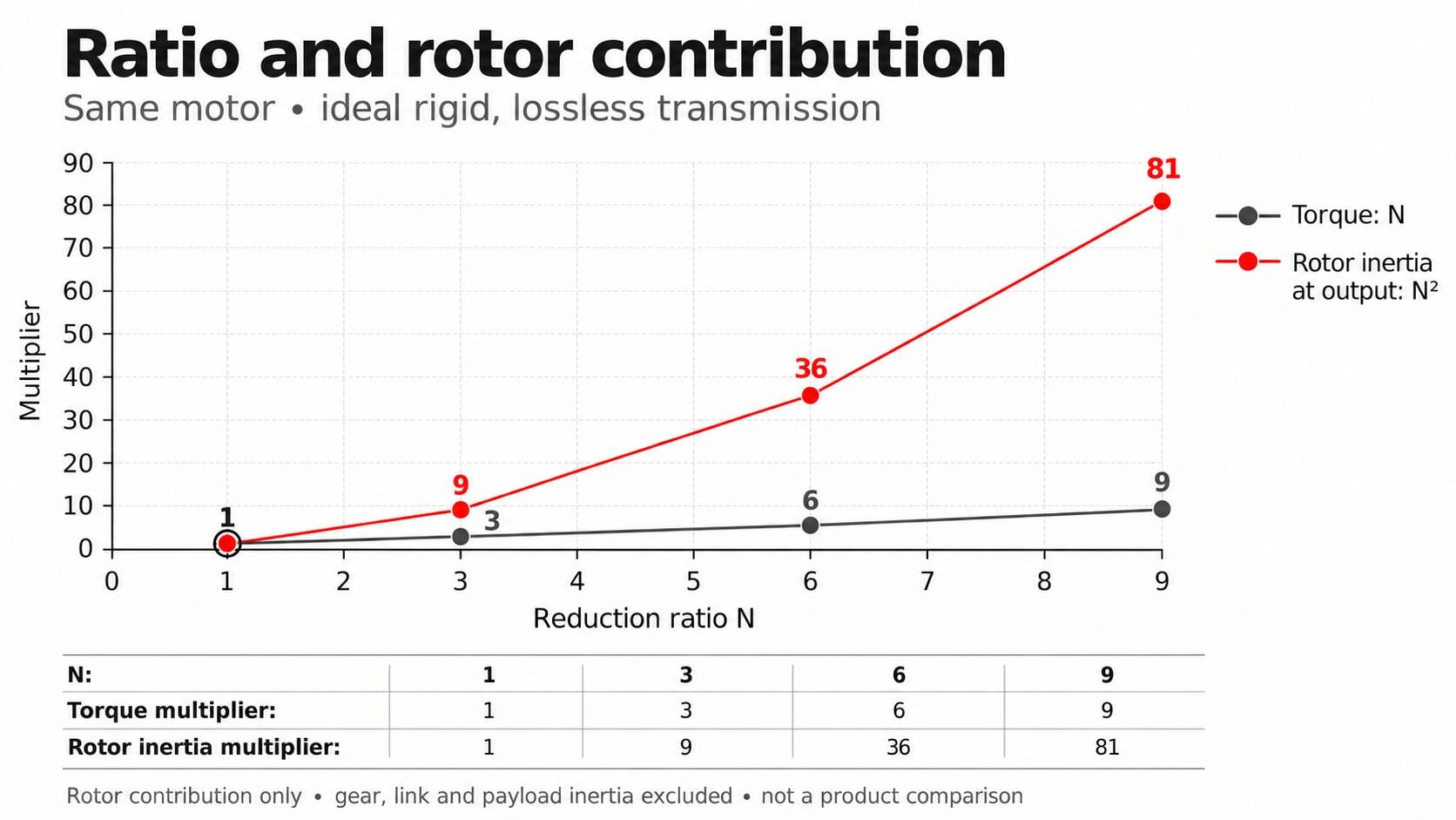
- How much rotor inertia is felt at the output? In an ideal rigid transmission, the motor rotor's contribution at the output is Jmotor × N². Holding rotor inertia fixed, reducing N lowers that contribution. Real total output inertia also includes gears, couplings, links and payload. A larger motor can change the comparison.
- How much resistance does external motion encounter? Lower reduction can help the design objective, but gearbox friction, seals, bearings, cogging, brakes and electrical state still matter. Measure the assembled joint under stated conditions; see the robot actuator backdrivability guide.
- How faithfully can commanded current produce useful output torque? Transmission losses and dynamics affect the relationship. Feedback, current calibration, controller behavior and output-side measurement must be evaluated together. A low ratio is not proof of torque accuracy or control bandwidth.
The inertia relationship and its direction are explained in MIT's robot transmission and reflected-inertia notes (external source) by Russ Tedrake. The notes are technical background, not an endorsement of SolisMotor.
QDD, direct drive and higher reduction: what differs?
| Architecture | Transmission description | Main question before selection |
|---|---|---|
| Direct drive | No reduction stage between motor and load | Can the motor sustain the required output torque within the size and cooling budget? |
| Quasi-direct drive | Motor combined with a low-ratio transmission | Does the complete joint balance torque, speed, inertia and backdriving resistance for the task? |
| Higher-ratio geared drive | More speed reduction for a given motor | Are output speed, transmission behavior, support loads and control performance suitable? |
Scroll within the table to read every column.
These are architectural distinctions, not a ranking of suppliers or a guarantee that one class is always more efficient, precise or robust. For the gearless starting point, the direct drive motor explanation covers the separate motor-to-load arrangement.
How does this relate to SolisMotor products?
SolisMotor's MG6010-8 low-ratio planetary joint actuator is a concrete product to investigate when evaluating a low-reduction design. Its current listing and product record agree on these fields:
| Published MG6010-8 field | Listed value | What remains to be verified for your application |
|---|---|---|
| Reduction | 8:1 planetary | Forward/reverse losses, friction and permissible transmission loads |
| Rated torque | 5.00 N·m | Rating speed, thermal conditions, mounting and continuous duty |
| Peak torque | 11.00 N·m | Allowed duration, starting temperature, current limit and repetition |
Scroll within the table to read every column.
These are published product values, checked on October 25, 2026. They are not values for the hypothetical calculation above. The listing does not, by itself, provide an independently verified backdrive-torque curve, impact limit or torque-control bandwidth. Confirm those requirements and the supplied feedback/drive configuration before calling the joint suitable for a particular QDD application. Do not infer a complete performance specification from “8:1.”
For legged-system context, the SolisMotor quadruped robot joint-drive solutions page describes sizing around torque, speed and duty. A general application page is not a tested robot case or a promise that every listed motor suits every leg joint.
What should an OEM request before choosing a QDD actuator?
Request the actual output duty, rather than comparing headline peak torque alone. The continuous torque vs peak torque guide explains why duration and thermal conditions matter. A useful review package includes:
- Output requirements: torque and speed over time, holding intervals, acceleration, load inertia and external disturbances.
- Transmission evidence: exact ratio, efficiency conditions, breakaway/running resistance, backlash or lost motion, stiffness and load limits.
- Electrical and thermal limits: supply range, drive current limits, continuous-duty conditions, cooling path, temperature sensing and power handling during deceleration.
- Mechanical and control interfaces: output bearing loads, mounting drawing, encoder location, supported control modes, communications and fault behavior.
- Validation conditions: what is measured, where torque is measured, powered/braked state, temperature, duty and acceptance criteria. Human-contact or impact requirements need system-level validation.
FAQ
Is a QDD motor a direct drive motor?
No. A QDD actuator retains a reduction transmission; direct drive has no reduction gearbox between motor and load. Both still require support mechanics, feedback, a drive and thermal design.
Is every 6:1 or 8:1 actuator automatically a good QDD joint?
No. Those ratios describe reduction, not the whole actuator's behavior. Motor inertia, transmission losses, bearings, drive settings and the required duty determine whether the design meets the application.
Does QDD guarantee safe or effortless backdriving?
No. Evaluate the torque needed to start and sustain external motion under stated electrical, brake and temperature conditions. Backdrivability alone is not a robot safety assessment.
Can I select a joint using peak torque alone?
No. Verify continuous torque at the operating speed and cooling conditions, then check the allowed peak duration and repetition. Also verify mechanical loads and the complete torque–speed envelope.
To discuss a real design, send the output torque–speed duty, load inertia, cooling arrangement and installation drawing for a SolisMotor low-ratio robot joint actuator review.