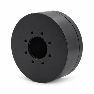
MG3505-8
 MG3505-9
 MG3505-36
 MG4315-8
 MG6010-6
 MG6010-8
 MG4305-10
 MG4310-10
 MG4310-36
 MG4310-40
 MG3510-8
 MG3510-64
 MG6010-36
 MG6010-48
 MG8108-6
 MG8108-8
 MG8108-36
 MG8108-48
 MG8115-6
 MG8115-9
 MG8115-36
 T-4024
 T-4929
 T-6034
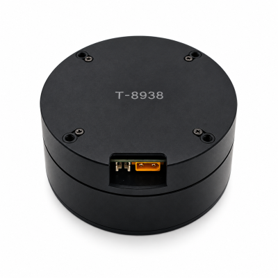
 T-8938
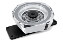
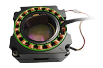
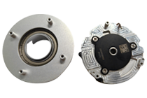
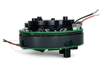
What Is Backdrivability in a Robotic Actuator?
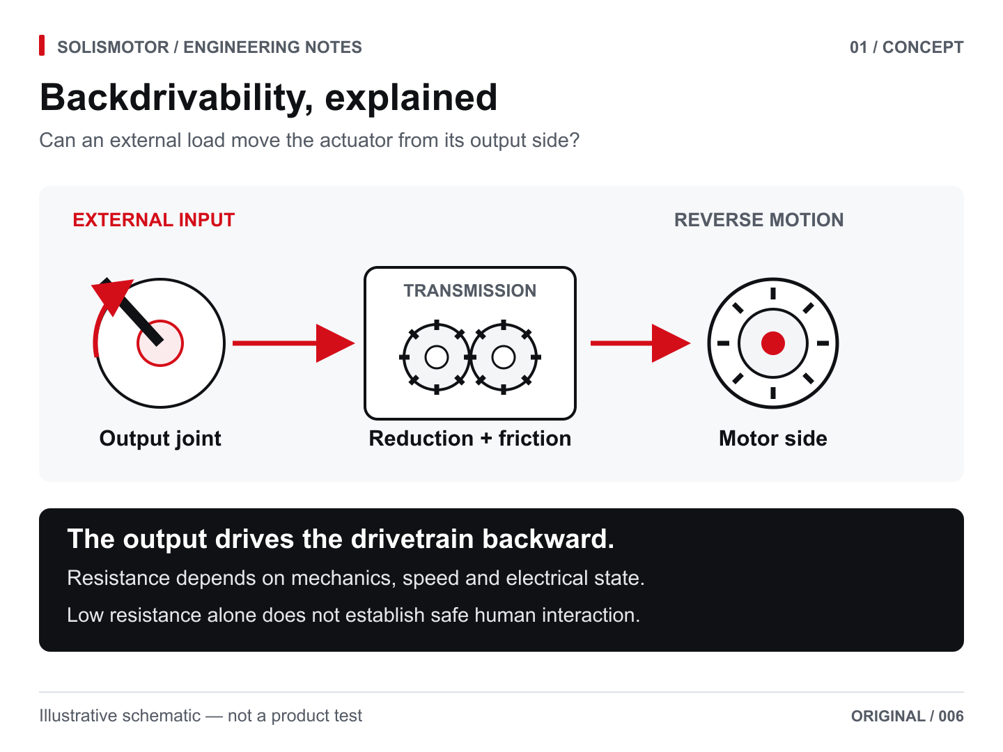
What is backdrivability in a robotic actuator? It is how readily external torque at the output moves the joint and drives its transmission and motor in reverse. Compare output breakaway torque, resistance while moving, reflected inertia, brake status, and the drive’s electrical state under the same test conditions. A hand-push test alone cannot establish a repeatable backdrivability specification or safe human interaction.
For a rotary robot joint, output torque and motion only become meaningful when the tested assembly, controller state, and brake state are declared. “Backdrivable” alone is not a complete performance specification.
Robot actuator backdrivability matters when a joint must yield to contact, be repositioned by hand, or respond to ground impacts. The relevant question changes with the application: how much torque starts motion, how much sustains a particular speed, and how the joint responds to acceleration or impact are different questions. For wearable interaction, the exoskeleton robot joint drive solution provides application context, not a measured backdriving value or safety certification.
Define the boundary before comparing actuators
A bare gearbox and a complete joint can behave differently. State whether the test includes the motor, gearbox, output bearings, seals, brake, installed link, and controller. Also distinguish passive mechanical behavior from the behavior of an energized joint under torque, position, or impedance control. Impedance control adjusts the relationship between motion and force; it does not change the physical hardware into a frictionless mechanism.
Use three separate descriptions when specifying a joint. Report output-side torque in N·m (or another explicitly declared unit) and state the measurement point:
| Measurement | What it answers | Conditions to record |
|---|---|---|
| Breakaway torque at the output | How much external torque initiates motion from rest? | Starting angle, direction, temperature, brake and electrical state |
| Running resistance | How much torque sustains imposed output motion? | Output speed, direction, angular range, thermal condition and load |
| Dynamic response | How does the assembly resist changing motion or contact? | Acceleration or excitation, inertia, robot configuration and controller settings |
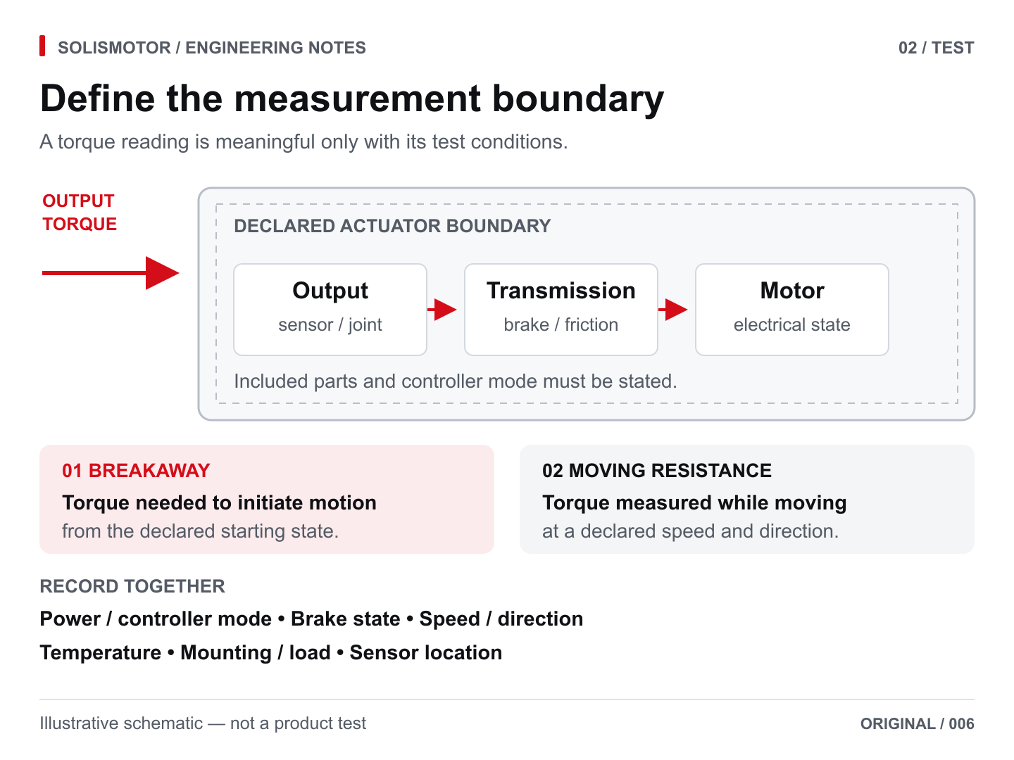
A hand test may reveal sticking or notchy motion, but it does not establish a repeatable torque-speed curve. Nor does a low breakaway value establish low inertia during a rapid interaction. Wensing et al. distinguish velocity-dependent and inertia-dependent aspects of backdrivability in their 2017 MIT Cheetah actuator study.
Why gear ratio and inertia matter
For a simple ideal reduction, define N = motor speed / output speed. The motor rotor's inertia, referred to the output coordinate, is:
J_reflected = N² × J_motor
This relation describes the rotor contribution under a rigid transmission assumption. It is not a formula for breakaway torque, and it does not include every moving component. The installed joint also has gear, link, and load inertia. Northwestern's Modern Robotics, Section 8.9, derives this ratio-squared effect from rotor kinetic energy.
For a hypothetical rotor inertia of 0.00002 kg·m², a 10:1 reduction contributes 0.002 kg·m² at the output; a 50:1 reduction contributes 0.05 kg·m². With the same rotor, that contribution is 25 times larger. These are illustrative calculations, not SolisMotor test results, and they say nothing by themselves about friction or allowable load.
Reducing the ratio can reduce this contribution, but the motor may then need to supply more torque and may have a different rotor inertia. Compare actual motor-transmission combinations instead of optimizing the ratio alone. For forward sizing context, see calculate robot joint torque, inertia and gearing; its forward-drive formulas do not replace reverse-operation measurements.
Friction, efficiency and cogging change the result
Gear friction, lubrication, temperature, alignment, and input-side motor resistance all affect reverse motion. A forward-running efficiency figure at one operating point cannot establish the output torque required to start backdriving. Ask for reverse-operation data under relevant conditions. maxon's technical guidance emphasizes evaluating the complete motor-gear combination and staying within permissible gear torque during assessment.
Motor cogging is another source of resistance: magnetic geometry can create preferred rotor positions even without applied current. The guide to what cogging torque means for low-speed joint motion explains this unpowered, low-speed effect. It differs from torque ripple caused by commutation. Consequently, removing the gearbox does not guarantee smooth, resistance-free manual motion, and field-oriented control alone does not establish cogging compensation. Direct-drive motor options for robot joints show a no-reduction product category, not verified backdrivability for any particular model. maxon's cogging guidance makes these distinctions explicitly.
Likewise, a transmission label does not settle the question. Harmonic Drive's SHF/SHG catalog publishes output-side backdriving torque values under stated conditions. That is evidence that “strain-wave gear” should not automatically be read as “impossible to backdrive.” It is not evidence that every assembled strain-wave joint will meet a particular hand-guiding requirement.
The electrical state belongs in the specification
“Motor off” is ambiguous. A drive may leave phases in a high-impedance state, connect phases for electrical braking, or remain energized in a control mode. These states can produce different resistance to externally imposed motion. A position loop may oppose displacement; an appropriately configured torque or impedance mode may allow yielding.
A published motor-driver data sheet describes different coast, recirculation, braking, and active spin-down states for a specific driver. That device-specific example shows why a stop command alone does not define a test state and says nothing about SolisMotor controllers. Record the actual drive configuration, current command, compensation settings, and brake release state.
Depending on the drive topology, a connected motor in a high-impedance state may still have semiconductor paths; externally imposed motion can also generate voltage. High impedance alone is therefore not proof of electrical isolation. Follow the drive manufacturer's instructions for externally driven operation, current limits, and energy handling. Do not improvise a test by shorting phases or disconnecting a live motor.
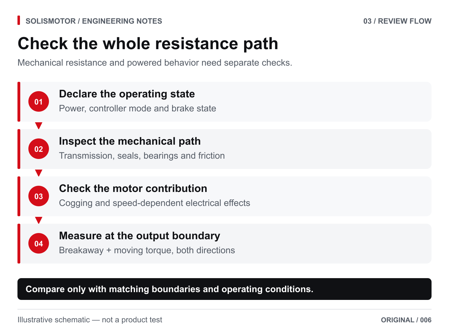
A practical evaluation plan
The following is an engineering comparison framework, not a standardized qualification procedure. Agree on the test method and acceptance limits for the actual application before comparing suppliers.
Backdrivability specification and comparison table
Use the same output boundary and test state for every robot arm joint motor or robot joint actuator in the comparison. Leave a field unreported rather than inferring it from a catalog label.
| Specification item | Report as | Why it matters |
|---|---|---|
| Output breakaway torque | N·m, both directions, multiple start angles | Captures the torque needed to initiate motion, including position-dependent variation. |
| Running backdrive resistance | N·m versus output speed and direction | Separates moving resistance from a static hand-push impression. |
| Rotor contribution to output inertia | kg·m², motor rotor inertia and reduction ratio stated | Shows one component of dynamic resistance; it is not a backdriving-torque rating. |
| Brake and electrical state | Released/engaged; coast, braking, or powered mode | Changes the measured response and must match the intended operating case. |
| Test boundary and environment | Included assembly, load, temperature, sensor location | Makes supplier results comparable and identifies excluded influences. |
- Define the use case. Specify whether the requirement is unpowered repositioning, powered hand guidance, or dynamic contact. Give the permitted external torque and required speed range.
- Identify the tested assembly. Record the exact motor, reduction, bearings, brake, firmware, and attached load. State which components are excluded.
- Control external influences. Support gravity-loaded links and document any gravity compensation. Account for fixture friction and sensor uncertainty; do not silently include them as actuator resistance.
- Measure from the output. Use a suitable torque transducer and motion measurement. If force is measured through a lever, calculate torque from the perpendicular moment arm: T = F × r_perpendicular.
- Separate starting and running results. Record breakaway torque at multiple starting angles in both directions. Then measure resistance over the relevant slow-motion speeds and angular range, within all component limits.
- Repeat the relevant states. Compare the documented passive state with any required powered mode. Record temperature, warm-up, lubrication condition, and repeatability.
- Evaluate dynamics separately. Where contact response matters, use an appropriately designed dynamic test and model. A slow rotation test cannot validate impact performance.
A useful supplier report identifies the configuration and reports torque against output angle or speed, rather than supplying only “yes” under backdrivability. Distinguish measured results from simulations, typical catalog values, and guaranteed limits.
Backdrivability and safety are separate requirements
An easily moved joint may also move under gravity when power disappears. Conversely, a joint that resists hand motion is not automatically a dependable load-holding device. The SHF/SHG catalog explicitly cautions against using backdriving torque as holding torque and calls for a failsafe brake for that purpose.
Holding and stopping must also be distinguished. For example, maxon's guidance for its specified holding brakes says they retain a stationary load rather than decelerate a moving one. The selected brake must suit the actual load and operating sequence. Releasing it during a test requires the load to be secured first.
Backdrivability can support interaction design, but it does not certify a robot as safe for human contact. Assess the complete machine, its motion and loads, protective measures, fault response, and intended use. Neither a gear ratio nor a manual push test replaces that assessment.
Applying the result to actuator selection
Use the robot joint motor and actuator options to identify candidate product categories. For system-level trade-offs beyond backdrivability, read the robot joint motor torque, heat and integration guide. Then request configuration-specific evidence against the same output-side test conditions. This article does not assign a measured backdriving torque or a safety rating to any SolisMotor model.
Technical references: Lynch and Park, Modern Robotics, Section 8.9; Wensing et al., Proprioceptive Actuator Design in the MIT Cheetah (2017); Harmonic Drive, SHF and SHG, page 53; maxon technical notes on backdrivability, cogging, and holding brakes; Texas Instruments, MCF8316A motor stop options. Numerical examples are hypothetical; the evaluation plan is an engineering synthesis.
Frequently asked questions
Is backdrivability the same as compliance?
No. Compliance describes deformation or displacement under load; backdrivability concerns driving motion back through the actuator. A spring can deflect without rotating the motor, while an actuator can be backdrivable without a deliberately soft spring.
Does low gear ratio guarantee low backdriving torque?
No. The motor, transmission losses, brake, and electrical state remain relevant. Ratio is one design variable, not a complete measurement.
Can powered hand guidance prove unpowered backdrivability?
No. Assistance or compensation may be active during hand guidance. The result applies to that powered configuration unless the unpowered state is tested separately.
Which number should a purchasing specification request?
Request output breakaway torque and running resistance under defined conditions, plus dynamic evidence if contact response matters. Set acceptance limits from the application rather than treating one number as universal.
Can a harmonic-drive robot actuator be backdriven?
It depends on the specific gear, motor, brake, and electrical state. Some strain-wave gear catalogs publish backdriving-torque values, but those values cannot be transferred to an assembled joint without checking the complete configuration and test conditions.
What should I compare for a cobot joint motor used in hand guidance?
Compare output breakaway torque and running resistance in both directions, then evaluate the powered guidance mode and dynamic response separately. A comfortable hand-guided feel does not establish unpowered backdrivability or certify human-contact safety.
For an application-specific comparison, share your output-side torque target, speed range, drive and brake state, and integration constraints when you contact SolisMotor about robot joint actuator selection.