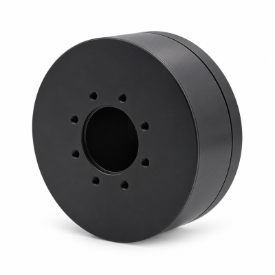
MG3505-8
 MG3505-9
 MG3505-36
 MG4315-8
 MG6010-6
 MG6010-8
 MG4305-10
 MG4310-10
 MG4310-36
 MG4310-40
 MG3510-8
 MG3510-64
 MG6010-36
 MG6010-48
 MG8108-6
 MG8108-8
 MG8108-36
 MG8108-48
 MG8115-6
 MG8115-9
 MG8115-36
 T-4024
 T-4929
 T-6034
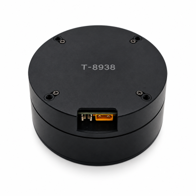
 T-8938
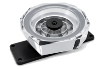
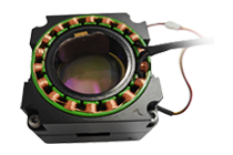
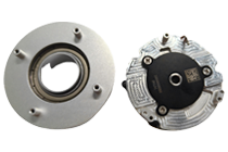
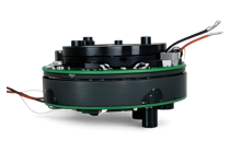
What Is a Frameless Torque Motor? Components, Integration, and Selection Checks
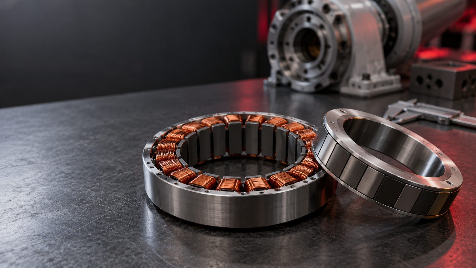
What is a frameless torque motor? It is a brushless motor supplied chiefly as a separate stator and rotor for installation inside a machine's own structure. The integrator normally supplies the housing, bearings, output structure, feedback, drive, and heat path. “Frameless” describes the package, not a promise of direct drive or a complete robot joint. Compare torque ratings only under stated speed, cooling, and duty conditions.
This guide explains the integration boundary rather than assigning a specification to a particular product. SolisMotor's robot joint motor portfolio and architecture overview shows adjacent assembled joint options. A frameless concept on a category page is not a substitute for a configuration-specific drawing and test report.
What is actually supplied?
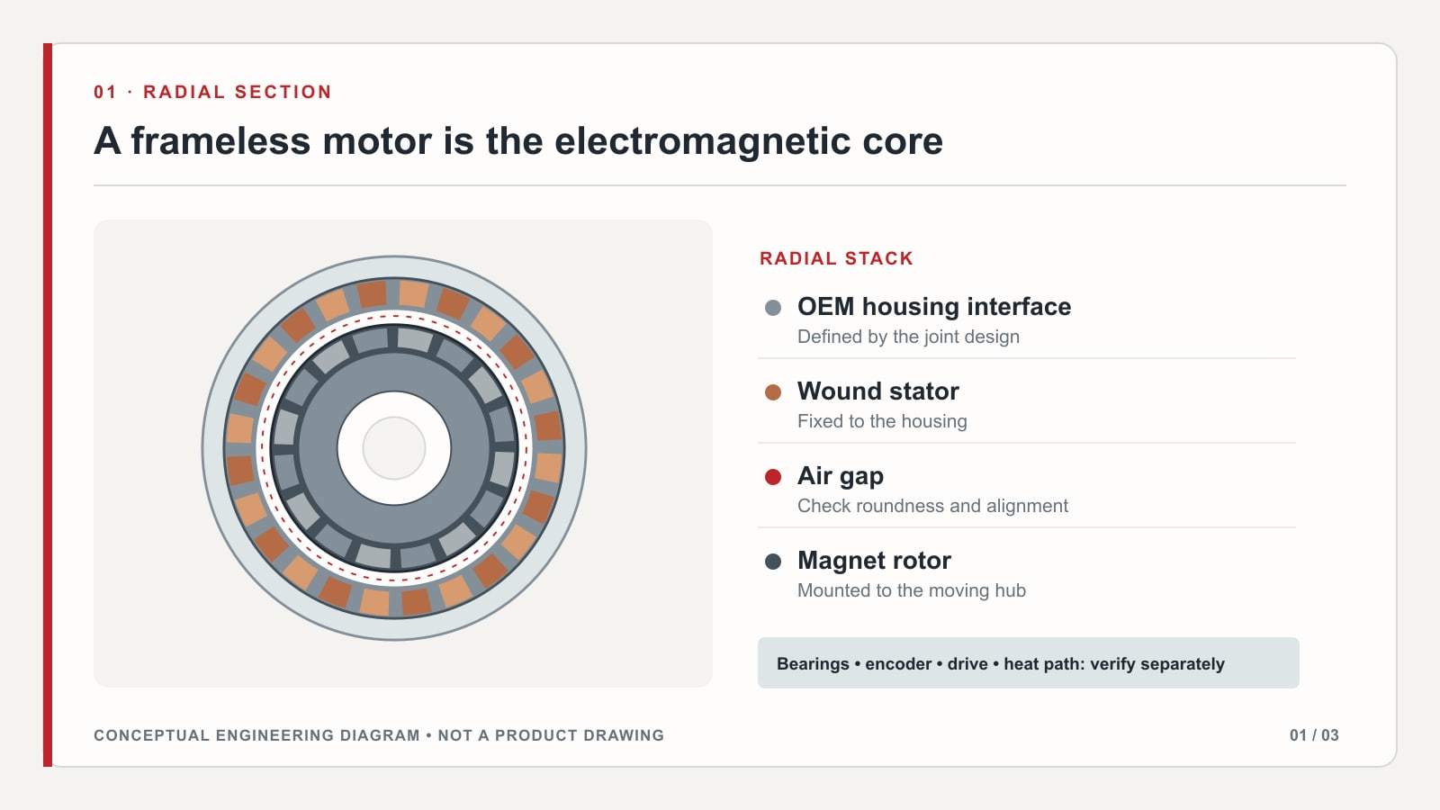
The stator is the stationary, wound part. In a common permanent-magnet design, the rotor carries the magnets. The controlled clearance between them is the working air gap. A frameless set is intended to become part of the host machine's mechanical and thermal structure; it is not, by itself, a supported output axis.
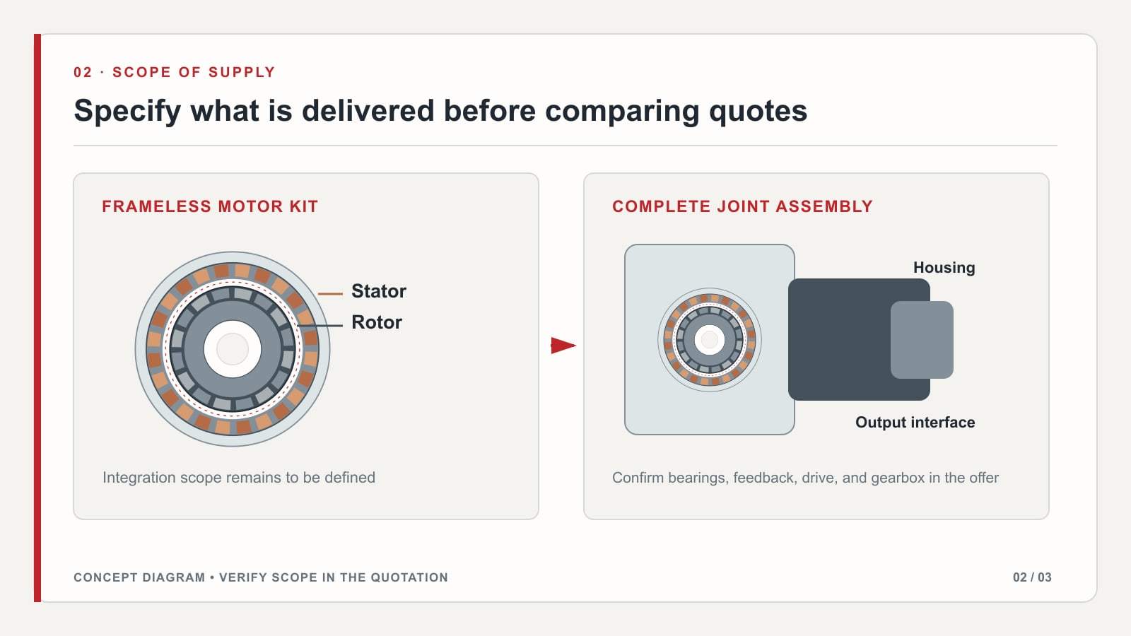
The exact delivery boundary varies. A supplier may offer a rotor hub, temperature sensor, or other options, but these cannot be assumed from the word “frameless.” Request the assembly drawing and bill of materials before assigning mounting or performance responsibilities.
| Element | Typical frameless-set boundary | What the integrator must confirm |
|---|---|---|
| Stator and rotor | Electromagnetic components supplied as a matched set | Dimensions, materials, lead exit, and rotor retention instructions |
| Housing and heat path | Usually part of the host machine | Stator mounting fit and the validated route for heat into the structure |
| Bearings and output structure | Usually outside the motor set | Radial and axial loads, stiffness, alignment, and service access |
| Feedback and servo drive | May be separate or offered as options | Commutation, position reference, electrical limits, and controller compatibility |
| Gearbox and brake | Architecture-dependent additions | Whether reduction, holding, or fail-safe behavior is required |
The table describes common design boundaries, not the contents of every supplier's kit. An assembled robot joint motor can include several of these missing functions, but its own datasheet must define which ones. For the purchasing distinction, see the servo motor versus robot joint module comparison.
Does frameless mean direct drive?
No. “Frameless” says how the motor is packaged. “Direct drive” says the motor drives the load without a reduction gearbox. A frameless motor can be integrated either way. For example, a published robotic-joint study combined a frameless BLDC motor with a planetary reducer, encoder, and controller; its measured results belong to that research prototype, not to a SolisMotor product (Korean Society for Precision Engineering study — external source).
With direct drive, there is no gearbox backlash, but stiffness, torque ripple, position accuracy, and heat still depend on the complete design. With reduction, compare motor-side torque and speed separately from output-side values, including efficiency and gearbox behavior. The direct-drive versus harmonic-drive robot-joint guide develops that architectural choice.
Which specifications matter after integration?
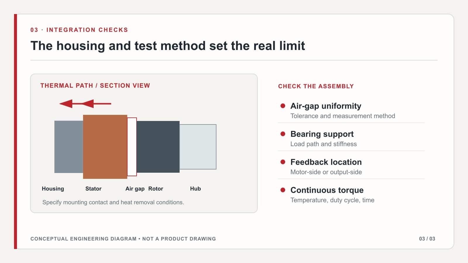
A torque number without its test boundary is not a usable joint specification. Continuous torque depends on the installed heat path and stated thermal limit. Peak torque is meaningful only with its allowed duration, starting temperature, current limit, and repetition pattern. Researchers measuring a brushless robot module reported continuous and peak torque against its thermal behavior; those prototype numbers must not be transferred to another design (Polish Academy of Sciences journal study — external source).
| Check | Ask for this condition or document | Why it changes the decision |
|---|---|---|
| Continuous torque | Speed, ambient temperature, cooling, mounting, winding-temperature limit | A different housing or coolant path can change the sustainable operating point |
| Peak torque | Peak current, allowable duration, starting temperature, repeat interval | A momentary number is not a continuous-duty rating |
| Torque-speed envelope | Supply voltage, current limit, drive method, speed range | The required torque must be available at the required speed |
| Air gap and concentricity | Supplier's nominal gap, tolerances, mounting and runout limits | Assembly variation can change electromagnetic behavior |
| Bearings and output loads | Radial/axial loads, moments, stiffness, life target | The motor's rotor is not a substitute for a rated joint bearing |
| Feedback and wiring | Encoder location, commutation reference, cable travel, connector plan | A through-bore or cable path alone does not enable unlimited rotation |
Air-gap control deserves explicit review. Experimental work at the University of Sheffield found that additional air gaps and eccentricities can affect cogging torque and torque ripple in permanent-magnet machines; the direction and size of the effect depend on the design and combination of tolerances (University of Sheffield experimental thesis — external source). Follow the selected motor's mounting drawing rather than adopting a universal gap value.
A practical selection and validation sequence
- Define the output motion. Record the torque-speed trace, acceleration, duty cycle, peak duration, external loads, and permitted envelope. The motor torque and speed calculation guide helps separate load-side requirements from motor-side values.
- Choose the mechanical boundary. Decide who owns the housing, bearing arrangement, rotor retention, feedback mounting, and any gearbox or brake. Obtain the relevant supplier drawings before designing the joint around assumed dimensions.
- Close the thermal and electrical boundary. Specify stator contact and cooling, ambient range, winding limit, drive voltage/current, feedback interface, and cable routing. Ask for continuous and peak ratings measured or modeled under comparable conditions.
- Validate the assembled axis. Check air gap and runout, then measure torque and temperature through the actual duty cycle. Verify the controller, brake state, and fault behavior at system level; a component rating alone does not certify a complete robot joint.
A frameless set can make sense when the machine already needs its own support structure and the team can validate mounting and cooling. An assembled joint may be a better fit when those integration tasks should come with the purchased module. Neither choice is automatically lighter, more accurate, safer, or more efficient. Compare the complete assembly against the same duty and service requirements.
Frequently asked questions
Is a frameless torque motor a complete actuator?
Usually not. Expect to integrate the electromagnetic set with a housing, bearings, output structure, position feedback, drive, and thermal path. Confirm the exact delivered scope in the supplier's drawing and bill of materials.
Is every frameless motor direct drive?
No. Packaging and transmission are separate decisions. A frameless motor can drive the output directly or through a gearbox; the selected architecture determines the output torque, speed, backlash, and mechanical trade-offs.
Does frameless construction eliminate cogging torque?
No. Cogging torque is a no-current interaction between rotor magnets and a slotted stator; manufacturing and installation tolerances can change it. Energized torque ripple additionally depends on current control. Do not infer a zero value from the absence of an external motor frame.
Can a hollow center carry cables through a rotating joint indefinitely?
Not by itself. A central passage can help route cables, but allowable twist depends on angular travel, anchoring, bend radius, and any rotary interface. Specify the motion before treating through-routing as a solution for continuous rotation.
Can I compare two continuous-torque figures directly?
Only after their speed, cooling, mounting, ambient temperature, and allowable winding-temperature conditions are aligned. If those conditions differ, request a comparable test or a documented thermal model for the intended assembly.
When discussing a bare motor set or an assembled joint with SolisMotor, send the torque-speed duty cycle, available envelope, cooling plan, bearing and feedback concept, and required cable travel through the SolisMotor engineering contact page. Ask for a configuration-specific drawing and test basis before selecting a model.