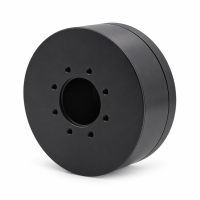
MG3505-8
 MG3505-9
 MG3505-36
 MG4315-8
 MG6010-6
 MG6010-8
 MG4305-10
 MG4310-10
 MG4310-36
 MG4310-40
 MG3510-8
 MG3510-64
 MG6010-36
 MG6010-48
 MG8108-6
 MG8108-8
 MG8108-36
 MG8108-48
 MG8115-6
 MG8115-9
 MG8115-36
 T-4024
 T-4929
 T-6034
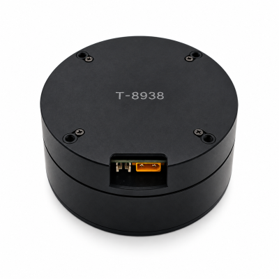
 T-8938
How to Choose Between a Robot Joint Module and a Servo Motor
Choose a servo-motor-based design if your team can engineer and validate the transmission, output support, drive and controls. Choose an integrated robot joint module if its documented configuration meets the joint's load, duty, feedback and installation needs with less integration work. A module can contain a servo motor; the terms describe supply scope, not a universal performance ranking. Verify the exact delivered configuration.
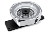
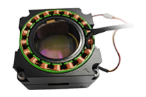
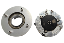
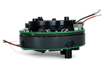
If you are comparing available hardware, start with the SolisMotor robot joint motor range, then check the drawing and included parts for the exact model. The distinctions below explain why a slow-moving servo may still need a gearbox, what feedback actually measures, and how to make a fair selection.
Swipe horizontally to read the full diagram →
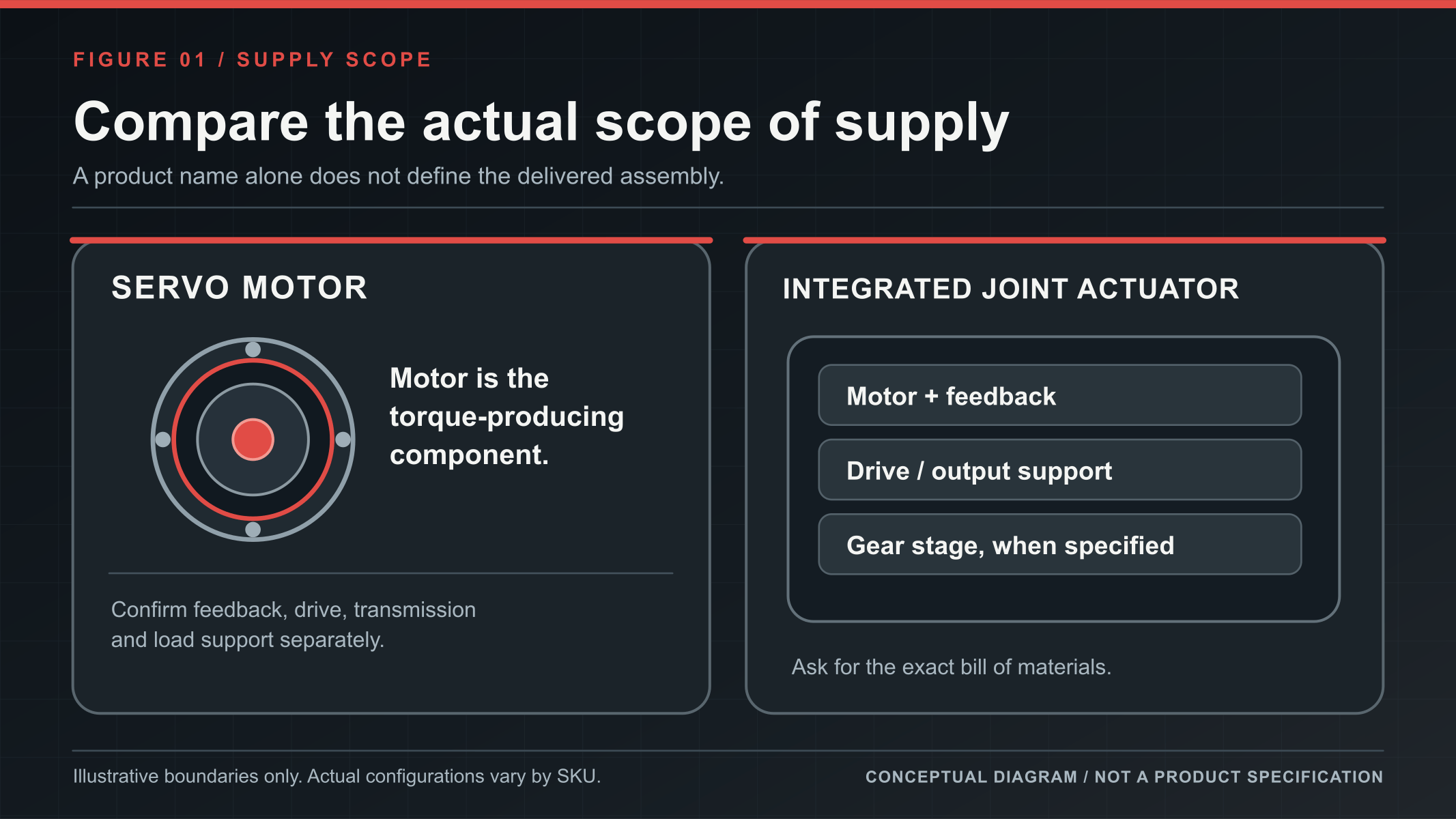
What is the difference between a servo motor and a robot joint module?
An electric motor creates torque. A servo system uses a drive and feedback to control motion toward a command. A robot joint actuator is a supplied assembly intended to move a joint; it may bring the motor, drive, sensors, transmission and output structure together. The categories overlap because a joint actuator may use servo control. “Joint motor” alone does not guarantee a complete module or a closed-loop drive.
Swipe horizontally to see all table columns →
| Supply level | Typical scope to investigate | What must be checked separately |
|---|---|---|
| Servo motor solution | Motor and specified feedback; the drive may be separate or included, depending on the model. | Drive, power supply, gearbox, output bearing, mounting and system validation. |
| Servo motor with integrated electronics | Motor, feedback, built-in drive and interfaces in a defined package. | Whether joint-output support, reduction, brake and robot-level power handling are supplied. |
| Integrated robot joint module | A model-specific combination of motor, feedback, drive and output interface; a geared version also includes its specified gearbox. | Exact bill of materials, allowable external loads, continuous duty, installation and robot-level control. |
“Integrated” describes the supply boundary, not an automatic improvement in accuracy. Compare the parts, installation space and engineering work needed to complete the same joint task, and request the current drawing and bill of materials for the ordering code.
How does servo control move a robot joint?
Suppose the controller commands an elbow toward 30°. The drive regulates motor current, the motor produces torque, and a position sensor reports what moved. The control system repeatedly compares the target with the measured position and adjusts its command. This measurement–comparison–correction loop is what makes the motion a servo task; it does not remove the need to design the load path or verify safety at robot level.
Swipe horizontally to read the full diagram →
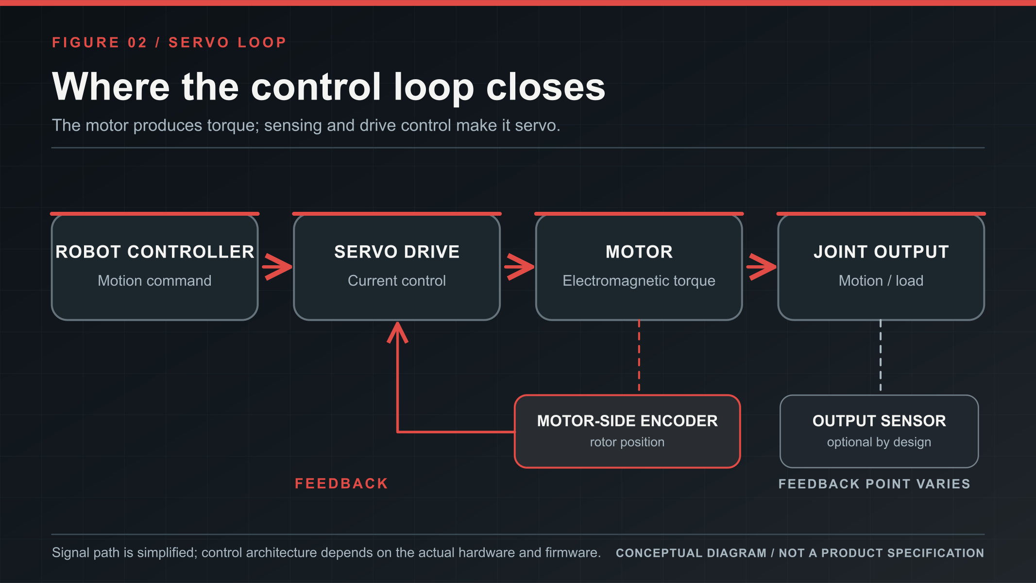
A drive inside the motor or joint package can perform local current, speed or position control. A separately mounted drive follows the same basic feedback principle but changes wiring, heat management and service access. The actual supported modes, update behavior and fault response still need to be checked for the chosen product.
If a servo motor can run slowly, why add a gearbox?
Turning slowly and carrying a load are different requirements. A lower speed command does not by itself raise the motor's continuous torque. Current limits, the torque–speed envelope and temperature still constrain what it can sustain. The continuous-versus-peak-torque guide explains why a short overload rating cannot replace a sustained-load check. A gearbox trades speed for output torque, subject to efficiency and the ratings of the transmission and supporting structure.
For a simple forward-driving estimate, output torque is approximately motor torque × reduction ratio × efficiency, while output speed is approximately motor speed ÷ reduction ratio. In a purely hypothetical example, a motor delivers 2 N·m at the relevant operating point, the gearbox ratio is 100:1, and efficiency at that point is assumed to be 90%. Estimated output torque is 2 × 100 × 0.90 = 180 N·m; output speed is one hundredth of motor speed. This is an illustration from the supplied engineering material, not a SolisMotor rating or a promise of achievable joint output. The motor, gearbox, bearings and housing must all survive the actual duty. A gearbox does not create power.
This explains why a slowly lifting arm may need reduction even when its requested speed is modest: sustained load torque, rather than speed alone, can be the limiting requirement.
Direct drive, lower reduction or higher reduction?
Direct drive removes gearbox friction, backlash and compliance from the transmission path, but the motor must provide the required joint torque within the size and thermal budget. A lower reduction ratio can balance output torque, speed and response. A higher ratio can increase output torque for a given motor torque, while making friction, elasticity, life and output-speed limits more important. There is no universal numerical dividing line between “low” and “high.” A well-controlled higher-ratio joint can still be designed for compliant behavior; the ratio alone does not prove how it will respond to contact. For interaction-sensitive axes, the backdrivability in a robotic actuator guide gives a separate way to frame external-force response.
Swipe horizontally to see all table columns →
| Route | Potential reason to investigate it | Evidence needed before selection |
|---|---|---|
| Direct drive | Minimal gearbox effects are valuable and the motor can sustain the full joint load. | Continuous torque, heat, size and output support. |
| Lower reduction | Speed, output torque and interaction response need a balanced compromise. | Real efficiency, current and thermal limits, impact and backdrivability. |
| Higher reduction | More output torque is needed within the available package and speed trade-off. | Gear life, friction, backlash/compliance, output-bearing loads and stopping behavior. |
These are design routes, not prescriptions for particular body parts. The same wrist can be a light adjustment axis or a heavy tool carrier. Use measured loads, not the joint's name, to choose a route. The related SolisMotor robot joint motor selection guide provides a complementary sizing workflow.
Which control mode and feedback point do you need?
Position control asks where the joint should go; speed control asks how fast it should move; current or motor-torque control asks for a motor-side effort. Some hybrid commands combine target position and speed with feedback gains and a feedforward torque term. Such a command can shape the response to a disturbance, but a listed mode is not proof of output-force accuracy or of a particular robot-level behavior.
The measurement point matters. A motor-side encoder measures rotor position. With a gearbox between the rotor and the load, it does not directly reveal every output-side error. An output-side encoder measures joint angle more directly. Two encoders are not a torque sensor, and encoder bit depth alone is not the positioning accuracy of the complete joint. Likewise, torque estimated from motor current is not the same as measured joint-output torque after transmission losses and elasticity.
Swipe horizontally to read the full diagram →
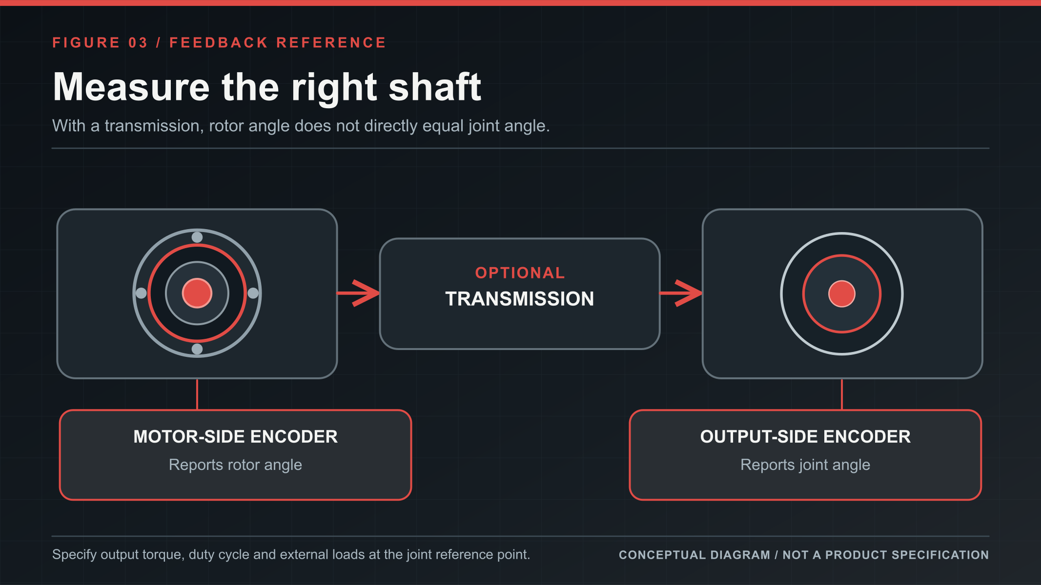
Ask which sensors are actually fitted, which shaft each rating refers to, and how the supplied controller uses the feedback. A protocol or mode name cannot answer those questions on its own.
What do hollow-shaft and integrated designs change?
A hollow passage can create space along the axis for cables, optical fibers or tubing. “Hollow shaft” describes geometry; “servo” describes controlled motion; “frameless” describes a motor supply or installation format; and “integrated” describes how components are packaged. These features can coexist, but one label does not establish the others. The SolisMotor hollow-shaft motor range is useful when cable routing is part of the mechanical decision.
A through-bore also does not make cables safe for unlimited rotation. Check cable twist limits and an appropriate rotating connection if continuous rotation is required. An integrated drive may reduce external interconnect cabling and component-matching work, yet it places electronics close to motor heat. A remote drive changes the cooling and service arrangement while adding cables. Neither layout is inherently more accurate or reliable.
Two SolisMotor examples show different supply boundaries
MG6010-8: a geared shoulder-joint assembly
The published SolisMotor MG6010-8 shoulder joint motor combines a brushless servo motor, an 8:1 planetary gearbox, drive electronics and encoder feedback. Its product page lists position, speed, torque and hybrid control modes. This illustrates a geared, integrated servo joint actuator; it does not establish the load capacity, installed sensors or control performance of every quoted configuration.
MG-H40-11: hollow routing with integrated servo electronics
The published SolisMotor MG-H40-11 hollow-shaft motor combines a brushless servo motor, built-in drive controller and single-turn absolute encoder; the page specifies a minimum 11 mm through-bore and lists position, speed and torque closed-loop control. This illustrates that hollow routing and integrated servo electronics can share a compact package. Do not infer an included gearbox, a complete joint output bearing or unlimited cable rotation from its name.
Both examples bring motor power, drive and feedback together, but their published transmission and mechanical features differ. Check the actual quotation, drawing and configuration before using either in a robot.
How should you choose for your robot?
Put four questions on the same comparison sheet for every candidate:
- What must the joint output do? Record continuous and peak torque, speed, peak duration, duty cycle, ambient temperature and cooling at the same reference shaft. Add radial, axial and moment loads.
- What is actually supplied? Confirm motor, drive, feedback, gearbox, output support, brake, connectors and software against the ordering code. Compare total installed-system work, not the unit price alone.
- What does the control system measure and handle? Check sensor locations, supported modes, actual feedback use, communication and fault behavior. Verify how the robot handles regenerated energy during braking or lowering a load.
- What evidence supports the intended duty? Request current drawings, continuous-duty conditions, thermal limits and a sample test plan. If power-off holding is required, verify a suitable brake or other holding mechanism; a high ratio is not a reliable safety lock by itself.
Power density and torque density are different comparisons: mechanical power is torque multiplied by angular speed, while torque describes rotational effort. State whether either density is per mass or per volume before comparing products. A joint holding still can have zero mechanical output power at zero speed while its energized motor continues to heat. Peak power or peak torque therefore cannot replace a continuous-duty check.
Choose a motor-based solution when its design freedom matters and your team can engineer and validate the missing transmission, support and controls. Choose an integrated robot joint module when a verified assembly meets the output, load, feedback and thermal requirements and its narrower integration scope is useful. Compare complete configurations at the same output shaft and duty condition; the product label is only the starting point.