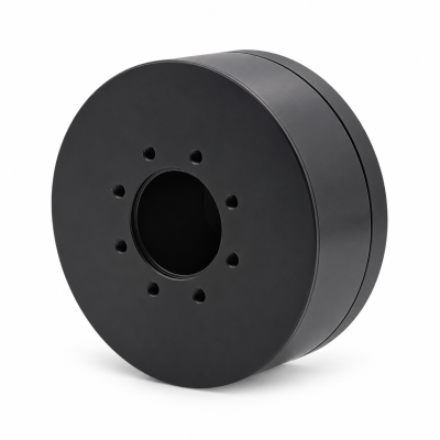
MG3505-8
 MG3505-9
 MG3505-36
 MG4315-8
 MG6010-6
 MG6010-8
 MG4305-10
 MG4310-10
 MG4310-36
 MG4310-40
 MG3510-8
 MG3510-64
 MG6010-36
 MG6010-48
 MG8108-6
 MG8108-8
 MG8108-36
 MG8108-48
 MG8115-6
 MG8115-9
 MG8115-36
 T-4024
 T-4929
 T-6034
 T-8938

How to Calculate Motor Torque and Speed
SOLISMOTOR · TECHNICAL GUIDES
Calculate motor speed from the required motion, then calculate torque from acceleration, inertia and external loads—all referred to the same shaft. For a simplified single rotary axis, the starting equation is T = Jα + T_gravity + T_external + T_friction, with each load term defined as the signed torque the motor must supply to overcome that effect. Check the full cycle against the motor and drive's peak limits, continuous thermal capability and torque-speed envelope.
A power calculation alone cannot establish the required starting torque or the torque needed to accelerate a load. This guide develops the calculation step by step for engineers and OEM teams preparing an axis requirement.
If you are still defining the joint architecture, start with the robot joint motor selection criteria, then use the calculation below to turn the chosen motion into a torque–speed requirement.
1. Define the shaft, units and sign convention
Start by naming the reference shaft: the motor shaft or the transmission output. Torque at one shaft and speed at another do not form a valid operating point.
Swipe the table horizontally to view all columns.
| Quantity | Symbol | SI unit or conversion |
|---|---|---|
| Torque | T | N·m; 1 N·m = 1,000 N·mm |
| Rotational inertia | J | kg·m²; 1 kg·cm² = 0.0001 kg·m² |
| Angular speed | ω | rad/s; ω = 2πn/60 when n is in rpm |
| Angular acceleration | α | rad/s²; α = Δω/Δt for constant acceleration |
| Mechanical shaft power | P | W; P = Tω |
Choose a positive rotation direction and retain signs throughout the calculation. With positive speed, positive torque delivers mechanical power and negative torque absorbs mechanical power. At zero speed, a motor can produce holding torque while mechanical shaft power is zero; electrical losses can still heat the motor.
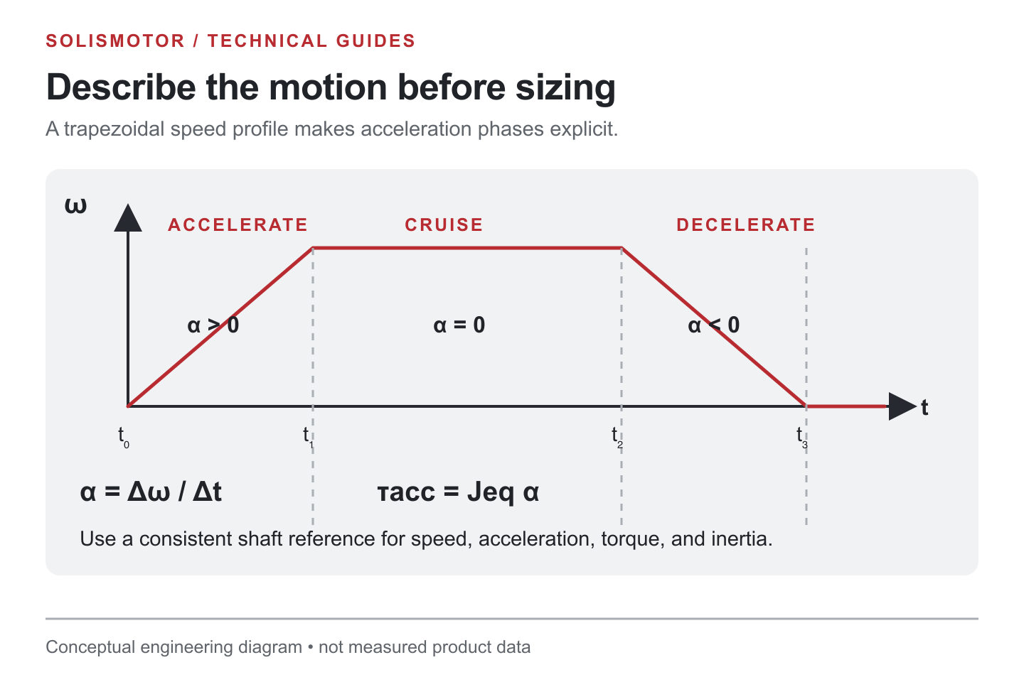
For a planar force perpendicular to the rotation axis, calculate the torque magnitude from T = F × r_perpendicular, where r_perpendicular is the perpendicular distance from the axis to the force's line of action. For a spatial force, use the component of the moment about the chosen axis. A force in newtons is not a torque until its moment arm and direction are included.
2. Convert the motion profile into speed and acceleration
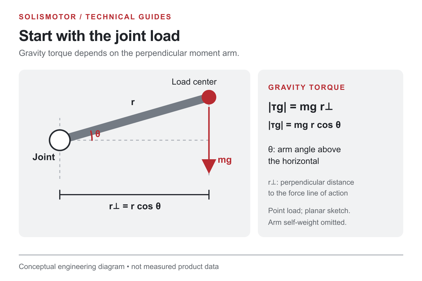
Describe the complete cycle: acceleration, travel at constant speed, deceleration, dwell and any holding period. Record the duration and direction of each segment.
If an axis turns through angle θ in time t at constant speed, ω = θ/t. For a symmetric trapezoidal move that starts and ends at rest, with equal acceleration and deceleration times t_a and a constant-speed interval t_c:
θ = ω_max(t_c + t_a)
Therefore, ω_max = θ/(t_c + t_a) and α_accel = ω_max/t_a. Use radians and seconds. If the acceleration and deceleration times differ, integrate the actual speed profile; the two triangular portions contribute ω_max(t_a + t_d)/2 to the angle.
An average speed calculated from total angle and total cycle time can hide a much higher moving speed. Similarly, a jerk-limited motion profile has changing acceleration; calculate torque using its actual α(t), rather than assuming one constant acceleration value.
3. Add inertia, gravity, external load and friction
For a rigid, single-axis model with constant equivalent inertia, use:
T_required(t) = J_total × α(t) + T_gravity(t) + T_external(t) + T_friction(t)
Here the last three terms represent the motor torque required to balance gravity, process loads and friction under the chosen sign convention. They can add to or subtract from the acceleration demand. Friction opposes motion, so its contribution changes sign when motion reverses; breakaway friction at rest may differ from running friction.
Include every rotating component in J_total at the selected reference shaft. For a concentrated mass at radius r, J = mr²; an extended part requires its actual mass distribution about that axis. A payload's center of mass can determine its gravity moment arm, but treating the entire payload as a point mass at that location can underestimate its rotational inertia.
Gravity torque is zero about an ideal vertical rotation axis because gravity acts parallel to that axis. For a horizontal axis, its magnitude depends on pose: T_gravity,magnitude = mg × r_perpendicular. Specify the angle convention before using a sine or cosine expression. A horizontal-axis dwell may require substantial holding torque.
This model has a defined limit. A robot with several moving joints can have configuration-dependent inertia, coupled motion and velocity-dependent terms. Northwestern University's Modern Robotics, Chapter 8.1, presents the broader dynamics framework. Use a multibody model when the single-axis assumptions do not represent the mechanism.
4. Convert output requirements through a reduction
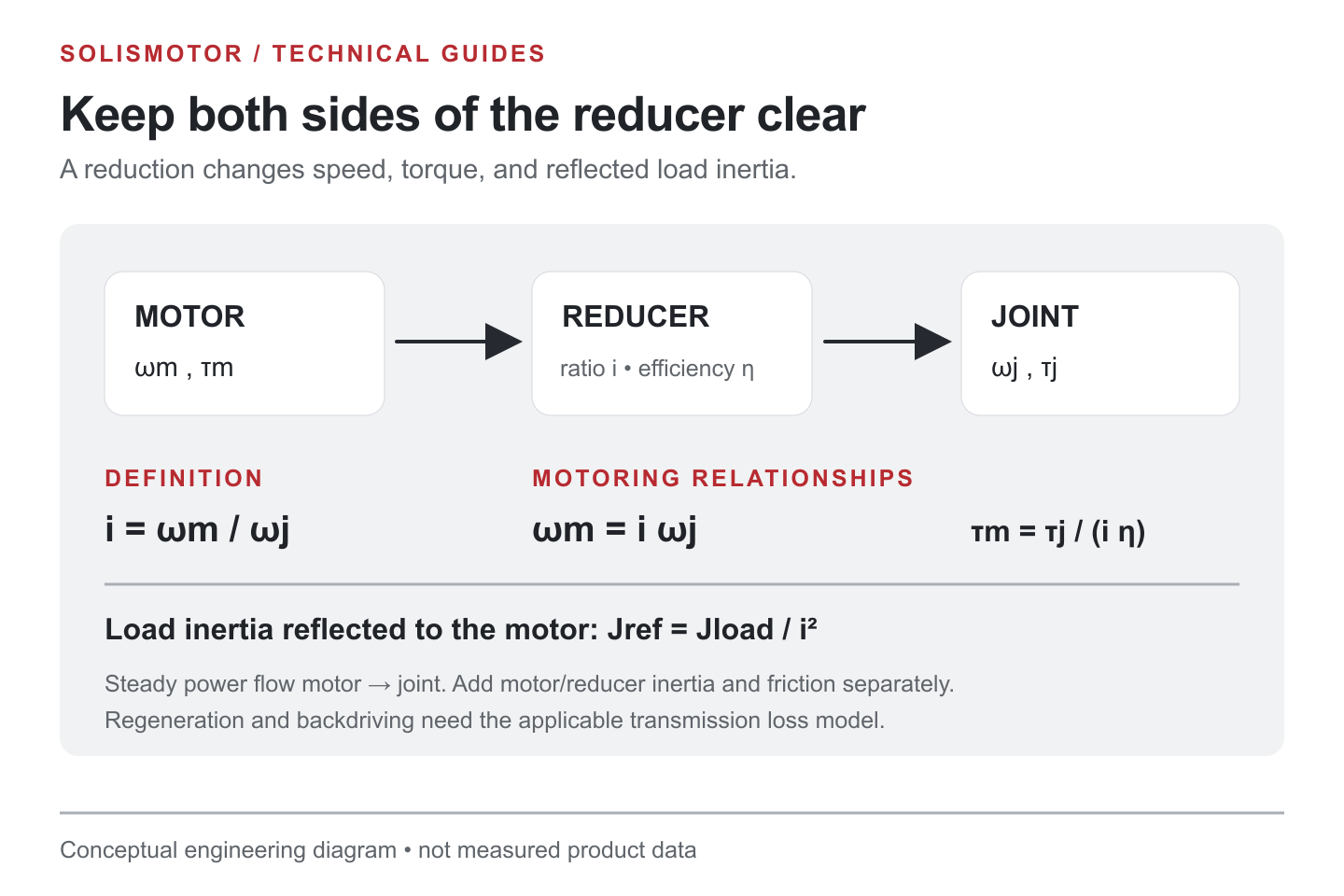
Define the gear ratio for a speed reduction as G = n_motor/n_output, with G greater than 1. For rigid gearing, the corresponding motor speed and acceleration magnitudes are:
The transmission choice changes the motor-side operating point. For that system-level decision, compare direct-drive and harmonic-drive robot joint architectures before finalizing a ratio.
n_motor = G × n_output
α_motor = G × α_output
With forward motoring efficiency η, the motor torque needed to supply an output load torque is:
T_motor,load = T_output/(η × G)
State what T_output includes. If it already contains output-load acceleration torque, do not add that same load inertia again. Motor rotor inertia and transmission component inertia still require their own treatment.
Under an ideal rigid-gear model, output-load inertia reflected to the motor is J_load,reflected = J_load/G². Conversely, the motor rotor contributes J_motor × G² when referred to the output. Northwestern University's Modern Robotics: actuation, gearing and friction (external source) explains the ratio-squared relationship. Keep the ideal inertia conversion distinct from an efficiency model, and use the transmission supplier's method for losses and component inertia.
For a separate hypothetical conversion example, an output requirement of 1.0 N·m at 90 rpm, a 10:1 reduction and an assumed forward efficiency of 0.80 give 900 rpm at the motor and 0.125 N·m for the motor-side torque term that supplies the output load. This is not a complete motor requirement: motor and transmission inertia, additional losses and operating limits still need checking. These assumptions are not SolisMotor product data.
Do not apply the forward efficiency equation unchanged during braking or backdriving. Reverse power flow, friction and the transmission's reverse behavior need an appropriate model or supplier data.
5. Worked example: a direct-drive rotary cycle
All values below are teaching assumptions, not measurements or specifications for a SolisMotor product. Consider a direct-drive, rigid axis rotating about a vertical axis. Assume:
- Total inertia, including rotor, coupling and load: J_total = 0.040 kg·m².
- Constant resisting torque during positive motion: 0.120 N·m.
- Acceleration from 0 to 90 rpm in 0.4 s, followed by 1.2 s at 90 rpm.
- Deceleration from 90 rpm to rest in 0.6 s, followed by a 0.8 s dwell.
- No gravity torque, no required holding torque during dwell and no additional losses in this simplified model.
The maximum speed is ω_max = 2π × 90/60 = 9.42478 rad/s. The 3.0-second cycle gives:
Swipe the table horizontally to view all columns.
| Segment | Time | Angular acceleration | Required motor torque |
|---|---|---|---|
| Accelerate | 0.4 s | +23.56194 rad/s² | 0.040 × 23.56194 + 0.120 = +1.06248 N·m |
| Constant speed | 1.2 s | 0 | +0.12000 N·m |
| Decelerate | 0.6 s | −15.70796 rad/s² | 0.040 × (−15.70796) + 0.120 = −0.50832 N·m |
| Dwell | 0.8 s | 0 | 0 N·m |
During deceleration, the axis still moves in the positive direction, so the assumed resisting torque still helps slow it. The motor provides the remaining negative torque.
For piecewise constant torque, the cycle RMS torque is:
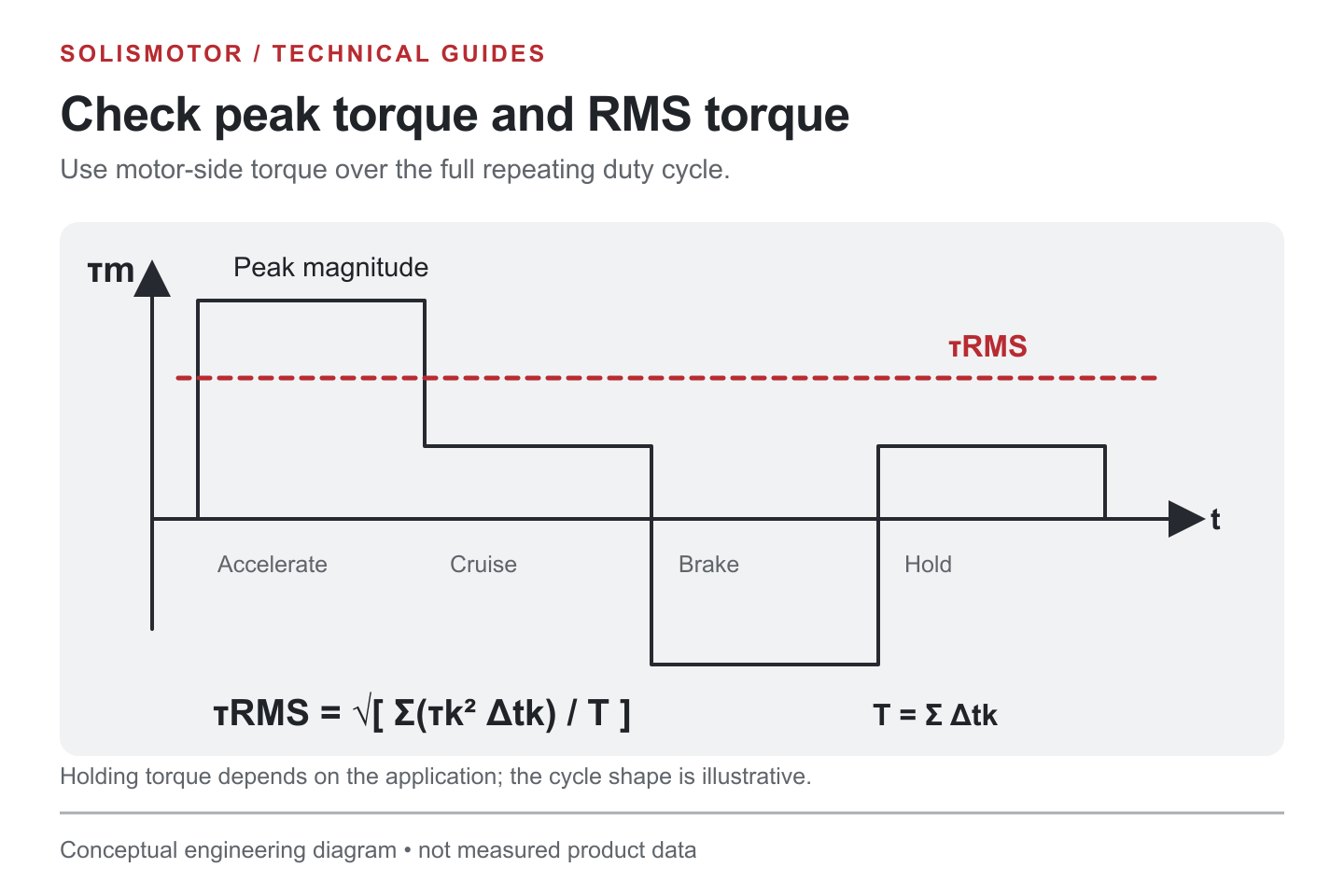
T_RMS = √[Σ(T_i² × t_i)/Σt_i]
T_RMS = √[(1.06248² × 0.4 + 0.12000² × 1.2 + (−0.50832)² × 0.6 + 0² × 0.8)/3.0] ≈ 0.45602 N·m
The largest absolute torque is approximately 1.06248 N·m. The highest positive mechanical power occurs at the end of acceleration and is approximately 1.06248 × 9.42478 = 10.014 W. This is mechanical shaft power, not electrical input power. Negative shaft power during deceleration requires checking how the actual drive and power supply handle braking energy.
The result is a requirement profile: it does not by itself prove that a particular motor can run the cycle.
6. Check peak torque, RMS torque and the torque-speed envelope
Use the calculated profile to make distinct checks:
- Peak capability: compare every short torque demand with the allowed peak torque, duration, current and repetition conditions of the motor and drive. A peak stall value does not establish available peak torque at speed.
- Thermal capability: RMS torque is a useful starting estimate when torque is proportional to current and the relevant motor parameters are sufficiently constant. Compare it with continuous capability under the actual mounting, cooling, ambient temperature and duty cycle. Account for speed-dependent losses, holding periods and cycle length relative to thermal response.
- Operating points: plot or check the paired torque and speed at each instant against the applicable envelope at the available supply voltage and drive current. Independently checking maximum torque and maximum speed can miss an invalid combination.
- Transmission and braking limits: check gear continuous and intermittent torque, speed, bearings, brake duty and energy handling separately.
San José State University's motor sizing notes (PDF, external source) treat peak torque, cycle RMS torque and maximum speed as separate sizing checks, including a comparison of calculated RMS demand with continuous torque capability. Neither a catalog continuous-torque label nor the RMS calculation substitutes for application-specific thermal validation.
For how torque, heat and packaging interact at the joint level, see SolisMotor's guide to robot joint torque, heat and integration. Once the duty profile and mounting conditions are known, compare candidate dimensions and integration options in the Robot Joint Motor range; request application-specific limits before selecting a motor.
7. A calculation checklist for an OEM requirement
- Define the reference shaft, positive direction and units.
- Record payload, geometry, inertia, process forces and gravity over the motion range.
- Build the full motion cycle and derive ω(t) and α(t).
- Calculate signed torque at that same shaft, including holding segments.
- Convert through the transmission once, with clearly stated ratio, loss assumptions and inertia boundaries.
- Calculate peak torque, RMS torque, speed and mechanical power; check braking-energy handling.
- Compare the complete profile with motor, drive and transmission limits, then validate with the intended installation.
Common mistakes are mixing rpm with rad/s, confusing N·mm with N·m, omitting motor rotor inertia, using the wrong ratio direction, counting load inertia twice, and assuming zero-speed dwell means zero torque. Another is using T = P/ω at or near zero speed: this relation converts known mechanical power at a nonzero speed; it does not calculate starting torque from a motor's nominal wattage.
To discuss a configuration after preparing the calculation, review SolisMotor's motor sizing and integration support. Share the torque-speed cycle, supply voltage, cooling conditions and mechanical constraints so the discussion starts from an explicit requirement.
FAQ
How do I calculate torque from power and speed?
At a known nonzero shaft speed, T (N·m) ≈ 9,549 × P (kW)/n (rpm). P must be mechanical power at that same shaft. This equation does not include an acceleration calculation and cannot determine holding torque at zero speed.
Is torque highest at maximum speed?
Not necessarily. Torque follows acceleration and load. In the teaching example, acceleration torque is constant throughout the acceleration segment, while mechanical power rises with speed. A gravity-loaded joint may reach maximum torque at a particular pose instead.
Can I use average torque instead of RMS torque?
Signed average torque can cancel positive and negative segments even though both produce current-related heating. RMS retains their squared contribution, but it remains an estimate whose validity depends on the motor, losses and thermal conditions.
Does a larger reduction ratio always solve a torque shortfall?
A larger ratio reduces the motor-side output-load torque term but raises required motor speed and changes reflected inertia. Gear losses and torque, speed and integration limits also matter. Recalculate the full cycle for the new ratio.
What information should accompany the calculation?
Provide the motion profile, inertia calculation, gravity and process loads, chosen reference shaft, transmission assumptions, duty cycle, supply voltage, ambient and cooling conditions, and required operating life. Label uncertain inputs so they can be measured or resolved before final sizing.