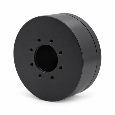
MG3505-8
 MG3505-9
 MG3505-36
 MG4315-8
 MG6010-6
 MG6010-8
 MG4305-10
 MG4310-10
 MG4310-36
 MG4310-40
 MG3510-8
 MG3510-64
 MG6010-36
 MG6010-48
 MG8108-6
 MG8108-8
 MG8108-36
 MG8108-48
 MG8115-6
 MG8115-9
 MG8115-36
 T-4024
 T-4929
 T-6034
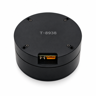
 T-8938
Strain-Wave Gear vs Planetary Gearbox for Robot Joints: How to Choose
Direct answer. Choose a strain-wave or planetary gearbox by matching the robot joint’s output torque–speed duty, space, lost motion, stiffness and heat limits. A compact high-ratio axis may favor strain-wave gearing; a lower-ratio, faster axis may favor planetary gearing. Compare complete assemblies under the same load, cycle and test conditions. Neither family guarantees accuracy, backdrivability or safety.
This guide compares two geared approaches, rather than ranking suppliers or unlike products. Browse the Robot Joint Motor Technical Guides for related selection methods.
Start with the joint's output requirement
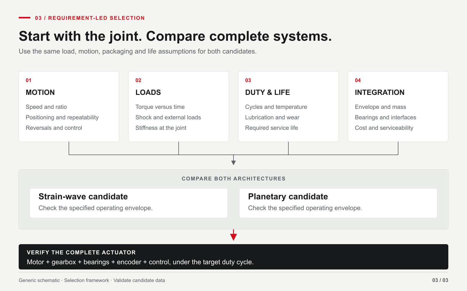
At the output flange, record continuous torque at the actual operating speed, short-duration peak torque and its permitted duration, maximum speed, acceleration, reversals, shock events and the total duty cycle. Add the available diameter and axial length, mounting and bearing loads, target positioning behavior, noise limits, ambient temperature and expected maintenance interval. If the joint must yield under an external load, specify that behavior and the control mode rather than assuming a gearbox family guarantees backdrivability.
The reducer is only part of the answer. Motor winding, drive current, encoder placement, bearings, brake and thermal path can change the behavior of the assembled joint. The distinction between a motor and a supplied joint assembly is explained in SolisMotor's robot joint module versus servo motor selection guide.
Architecture differences that affect selection
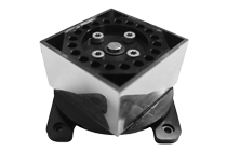
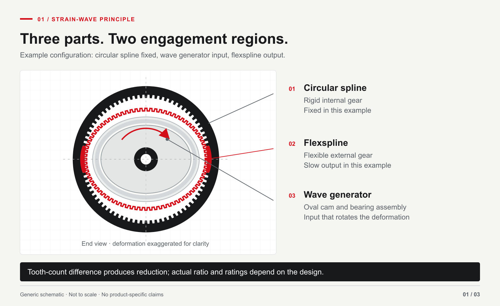
A common strain-wave arrangement uses a wave generator to deform a flexspline inside a fixed circular spline, with the flexspline as output. Its reduction and compact coaxial form can be useful when space is constrained. The selection consequence is to check both lost motion and load-dependent elastic twist; little free play does not mean infinite stiffness. NASA’s strain-wave component explanation (external technical source) supports this short structural background, not a product rating.
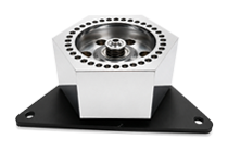
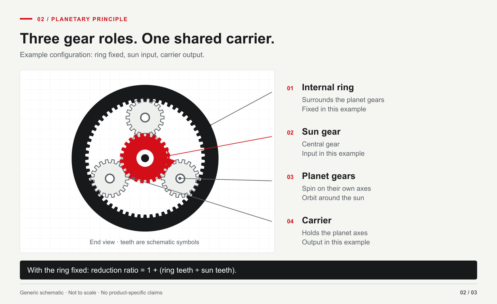
A planetary train uses a sun, planets, ring and carrier. Member arrangement, tooth counts and stage count shape the ratio and package. For selection, request the exact configuration and its measured behavior rather than assuming that every planetary joint shares one backlash or efficiency value. Jönköping University’s planetary-gear mechanics guide (external technical source) explains those configuration choices.
Comparison at the same output duty
The 2020 peer-reviewed review of compact gearboxes for robotics (external source) discusses transmission architectures and compares published specifications within a stated assessment framework. Its comparisons include supplier catalog data; the review does not test or endorse the SolisMotor products discussed here.
| Decision factor | Strain-wave gearing | Planetary gearing | Evidence to request |
|---|---|---|---|
| Reduction and package | Often considered for high reduction within a short coaxial package. | Single-stage lower ratios are common; multiple stages can raise the ratio. | Exact ratio, envelope drawing, mass and mounting interfaces. |
| Lost motion and stiffness | Low lost motion can coexist with measurable elastic twist. | Backlash and stiffness depend on tooth design, stage count and preload. | Output lost-motion and torsional-stiffness curves, load and test direction. |
| Heat and efficiency | Losses vary with ratio, load, speed, lubrication and temperature. | The same variables and stage count matter; no fixed efficiency advantage follows from the name. | Efficiency or input-power data across the actual duty cycle, plus thermal limits. |
| Shock and service life | Validate flexing-element fatigue, overload and bearing loads for the application. | Validate tooth, carrier and bearing loads, lubrication and overload conditions. | Allowable output loads, shock limits, life-test conditions and service guidance. |
| Control and backdriving | High ratio and friction may resist external motion, but behavior is assembly-specific. | Ratio, friction and drive control also govern external motion. | Measured breakaway torque, moving resistance, reflected inertia, brake and drive states, and control response. |
Swipe within the comparison table to see all four columns.
A third architecture may be appropriate when the joint does not need a gearbox at all. See SolisMotor's direct-drive versus geared robot joint selection for that separate decision; the present article compares two geared approaches.
Compare the same output task before comparing ratings
Use output speed n_out = n_motor / i and output torque T_out ≈ T_motor × i × η only as a first screen. Here i is ratio and η must correspond to the actual operating point. Neither equation proves a continuous rating, peak duration, thermal margin, accuracy or life. Different ratios can require different motors and drive settings to meet the same output task.
Give each candidate supplier one requirement sheet. Keep the demanded output motion, load, cycle, ambient temperature and measurement method the same; record each candidate’s actual motor, drive and reducer configuration separately. A high-ratio sample and a low-ratio sample cannot be ranked by their headline torque alone.
| Keep the required task the same | Record for each complete candidate | Decision rule |
|---|---|---|
| Output torque versus speed and peak-event duration | Motor operating point, ratio, drive limits and permitted output envelope | Reject a candidate that cannot cover the full required profile. |
| Reversal sequence, load and output measurement point | Lost-motion definition, stiffness curve and temperature | Compare results only when definitions and conditions match. |
| Cycle time, ambient conditions and mounting | Thermal path, losses, temperature limits and service assumptions | Validate sustained operation over the actual cycle. |
| External disturbance and required stopping behavior | Encoder arrangement, brake state, drive state and measured response | Verify system behavior and the application’s safety requirements separately. |
For available configurations and integration questions, review the Robot Joint Motor product group before selecting a candidate. A product listing starts the discussion; it does not replace application validation.
Five checks before choosing a joint gearbox
- Set the required output profile. Include torque versus speed, reversal frequency, peak-event duration, external loads and allowable temperature rise.
- Filter by ratio and envelope. Eliminate configurations that cannot meet output speed or installation space. Keep motor speed and voltage in the check.
- Distinguish backlash, lost motion and elastic twist. Request the supplier’s definitions and test method, including applied torque or torque sweep, output measurement point, reversal sequence and temperature.
- Validate the complete duty. Compare efficiency, thermal behavior, bearing capacity, shock limits, fatigue or wear life, and maintenance assumptions under your cycle.
- Test the controlled assembly. Confirm encoders, drive, brake, interfaces and real output response. Specify the brake and drive states during external-motion tests. SolisMotor’s robotic actuator backdrivability guide explains which conditions to record. Low lost motion or easy backdriving alone does not establish safe operation.
Common selection mistakes
“Low backlash means high accuracy.” It does not. Encoder location, elastic deflection, assembly tolerances, load direction and control tuning also affect position at the output.
“A higher ratio always improves the joint.” It reduces ideal output speed at a given motor speed. The useful torque gain depends on losses and allowable thermal load; reverse motion and control behavior must also be checked in the assembled joint.
“A published peak torque is a continuous rating.” Peak and continuous torque need their respective duration, speed and temperature conditions. Request the operating envelope, not a single headline number.
The joint drive solutions for humanoid robots page provides a related route for humanoid integration planning. Treat application-specific load, controls and validation requirements as part of the choice.
FAQ
Is a strain-wave gear always better for precise positioning?
No. Low lost motion can be useful, but positioning at the joint output also depends on torsional compliance, bearings, encoder arrangement, assembly and control. Compare measurements under the same load and direction.
Can a planetary gearbox be used in a robot joint actuator?
Yes. A planetary architecture can form part of an integrated robot joint actuator. Whether a candidate fits a particular axis depends on its torque–speed duty, package, feedback, control and verified load limits; the gear family alone is insufficient.
Which is easier to backdrive?
Neither label gives a reliable answer by itself. Compare the complete assemblies’ measured breakaway torque, resistance while moving, ratio and reflected inertia under matched conditions, with the brake and drive states specified.
What should an OEM send before requesting a recommendation?
Send a torque–speed and duty profile, target ratio or output speed, installation envelope, radial and axial loads, shock and temperature conditions, feedback and control requirements, and the expected validation plan.
To discuss a candidate for your axis, share that requirement sheet through SolisMotor’s robot joint engineering contact page.