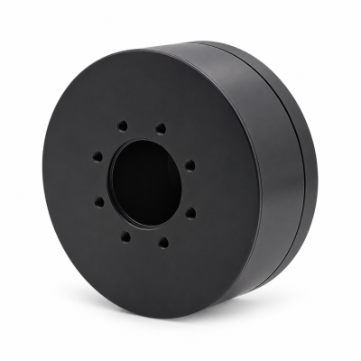
MG3505-8
 MG3505-9
 MG3505-36
 MG4315-8
 MG6010-6
 MG6010-8
 MG4305-10
 MG4310-10
 MG4310-36
 MG4310-40
 MG3510-8
 MG3510-64
 MG6010-36
 MG6010-48
 MG8108-6
 MG8108-8
 MG8108-36
 MG8108-48
 MG8115-6
 MG8115-9
 MG8115-36
 T-4024
 T-4929
 T-6034
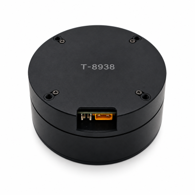
 T-8938
How to Select a Motor for Low-Voltage Robotics
Direct answer. Select a motor for low-voltage robotics by checking the required torque and speed against the voltage actually available at the drive, including battery discharge and wiring losses. Match the motor winding, drive current limits, feedback and repeated duty cycle. Verify maximum supply voltage and braking-energy handling too. A nominal voltage label alone cannot establish operating capability or compatibility across the complete robot.
Begin with the load and power-source specification, then compare the SolisMotor robot joint motor range. This guide treats “low voltage” as an application description for a DC-powered robot, rather than a certification or a universal safety classification. The selection question is whether the assembled axis can perform its task throughout the intended supply range.
1. Specify a voltage range at the drive terminals
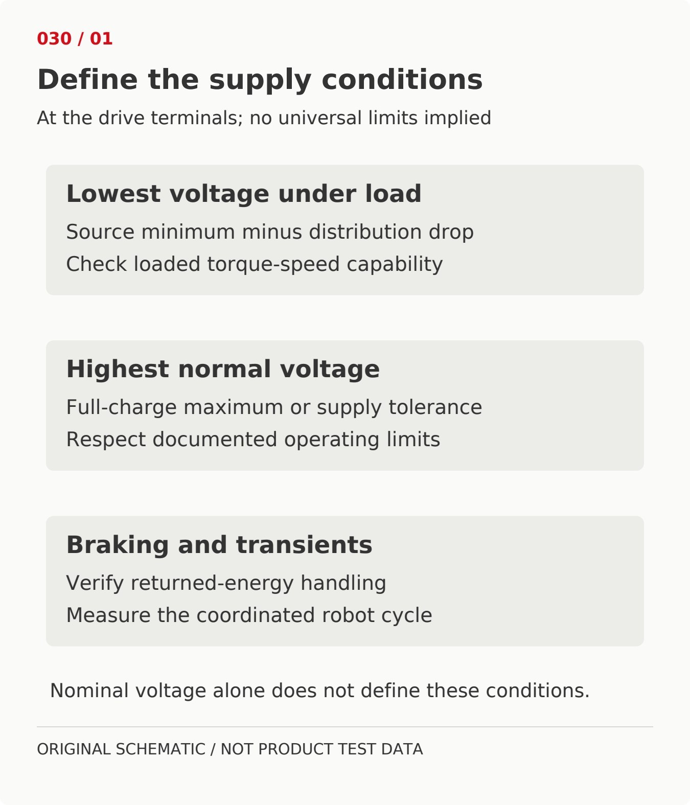
A battery's nominal voltage is a reference value, not the voltage the motor drive sees in every condition. Record the source's specified full-charge maximum, its minimum voltage under the intended load, and the drop between the source and drive. For a regulated supply, include its tolerance, transient response and current-limiting behavior.
| Condition | What to establish | Why it changes motor selection |
|---|---|---|
| Lowest operating voltage | Loaded source voltage minus distribution losses | Required torque and speed must remain achievable without an undervoltage trip |
| Highest normal voltage | Full-charge source maximum or regulated-supply upper tolerance | Must stay within the drive and other connected components' specified operating limits |
| Simultaneous joint movement | Combined demand at the actual motion timing | Source current limiting or voltage sag can affect several axes together |
| Braking or lowering a load | Whether and how the system returns mechanical energy to the DC bus | The source and drive need a documented way to handle returned energy |
| Warm, repeated operation | Voltage and current traces after the assembly heats up | A cold bench test does not establish repeated-duty capability |
Scroll within the table to read every column.
Use limits for the exact ordering configuration. A drive's absolute maximum is not a recommended operating target. Include voltage tolerances and transients according to the component documentation; do not invent a universal margin percentage.
2. Check loaded torque and speed, not only free-running RPM
Spinning a motor generates back electromotive force, or back-EMF, which increases with speed in the usual permanent-magnet motor model. The drive also needs voltage to establish current against winding resistance and inductance. Less available voltage can therefore restrict the torque-speed combinations the drive can maintain.
The MIT motor model of back-EMF, current and torque (external source), from the Fall 2021 control course, explains these relationships using a teaching motor. Its particular constants and simplifications do not describe a SolisMotor product. For a three-phase drive, ask for the applicable torque-speed curves and the current, voltage and control conventions behind them.
Motor KV is a useful winding-screening quantity, but a no-load speed estimate cannot prove that a loaded joint will reach the same speed. Compare candidate windings at the minimum installed bus voltage, with the intended drive and current limit. A lower-KV winding is not automatically the best choice: its torque-per-amp benefit must be evaluated alongside resistance, available voltage and required speed.
Ask whether the supplier's speed and torque refer to the motor shaft or geared output. Translate the joint's required motion to the same reference shaft before comparing curves. The separate robot joint module versus servo motor selection guide helps identify which drive, feedback and mechanical parts belong to the supplied assembly.
3. Estimate DC input current at a defined operating point
For steady positive motoring, motor-shaft mechanical power is:
P_shaft = torque × 2π × rpm / 60
If an explicitly stated efficiency covers the drive's DC input through to that motor shaft:
P_DC = P_shaft / efficiency
I_DC ≈ P_DC / V_bus
The last expression estimates average DC input current when bus voltage is approximately steady. With significant ripple, use synchronized voltage and current measurements; average power is the average of their product. This current estimate is not a phase-current limit or a complete power-supply sizing result.
Assumed example: 24 V versus 18 V at the drive
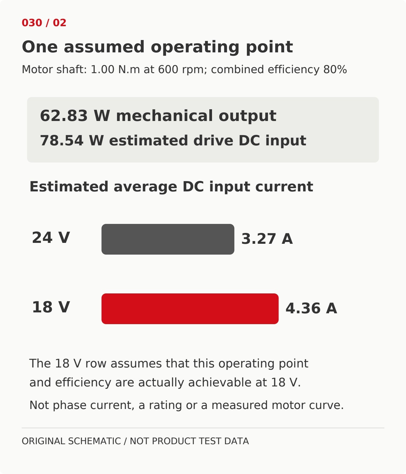
Assume a motor shaft delivers 1.00 N·m at 600 rpm. Assume combined drive-and-motor efficiency is 80% at that point. Mechanical power is about 62.83 W, requiring about 78.54 W at the drive's DC input.
| Assumed drive-terminal voltage | Estimated DC input power | Estimated average DC input current |
|---|---|---|
| 24 V | 78.54 W | 3.27 A |
| 18 V | 78.54 W | 4.36 A |
Scroll within the table to read every column.
These invented values illustrate a power budget, not a SolisMotor rating or a measured voltage curve. The 18 V row is valid only if the motor and drive can actually deliver the assumed torque-speed point at 18 V with the assumed efficiency. That must be checked separately. Gearbox losses, other robot loads and upstream distribution losses are outside this calculation.
At zero-speed holding, shaft power is zero while winding and drive losses may remain. Do not use a running-efficiency calculation to infer zero holding current. The robot joint motor power calculation guide separates shaft power, electrical input and holding conditions.
4. Separate bus current, phase current and cable losses
The DC source feeds a switching drive; it does not feed the motor windings as an unchanged DC current. Source current, phase RMS current, phase peak current and a controller's torque-current variable are different quantities. Check which definition appears in every motor, drive and protection specification.
For the same motor in its approximately linear magnetic region, torque demand determines the required torque-producing current through the applicable torque constant. Reducing DC-bus voltage does not by itself remove that current requirement. It may instead reduce the drive's ability to establish the required current at speed.
Distribution losses also consume voltage headroom. For a separate DC wiring example, assume 5 A passes through a total outgoing-and-return loop resistance of 0.10 Ω:
Voltage drop = I × R_loop = 0.50 V
Wiring heat = I² × R_loop = 2.50 W
The resistance includes the modeled loop, not just one wire. These are assumed values, not a cable-size recommendation. Choose cables, connectors, protection and routing from their documented electrical, thermal and mechanical requirements, then measure the installed drop under load.
For battery-powered humanoid packaging, the SolisMotor humanoid robot joint drive solutions provide application context. The actual bus distribution and joint selection still need a configuration-specific review.
5. Check braking energy and the repeated motion cycle
When the load drives the motor and the drive permits regenerative operation, mechanical energy can return to the DC bus. Confirm whether the selected source can accept that energy under the intended conditions, including a fully charged battery, or whether the system needs another approved energy-handling method. Do not assume every battery-management system or bench supply accepts reverse power.
Document the permitted drive behavior during overvoltage, undervoltage, current limiting and loss of feedback. A protection trip that interrupts a loaded axis is also a motion-control problem. Evaluate the required controlled response within the robot's system design; do not disable a limit to pass a test.
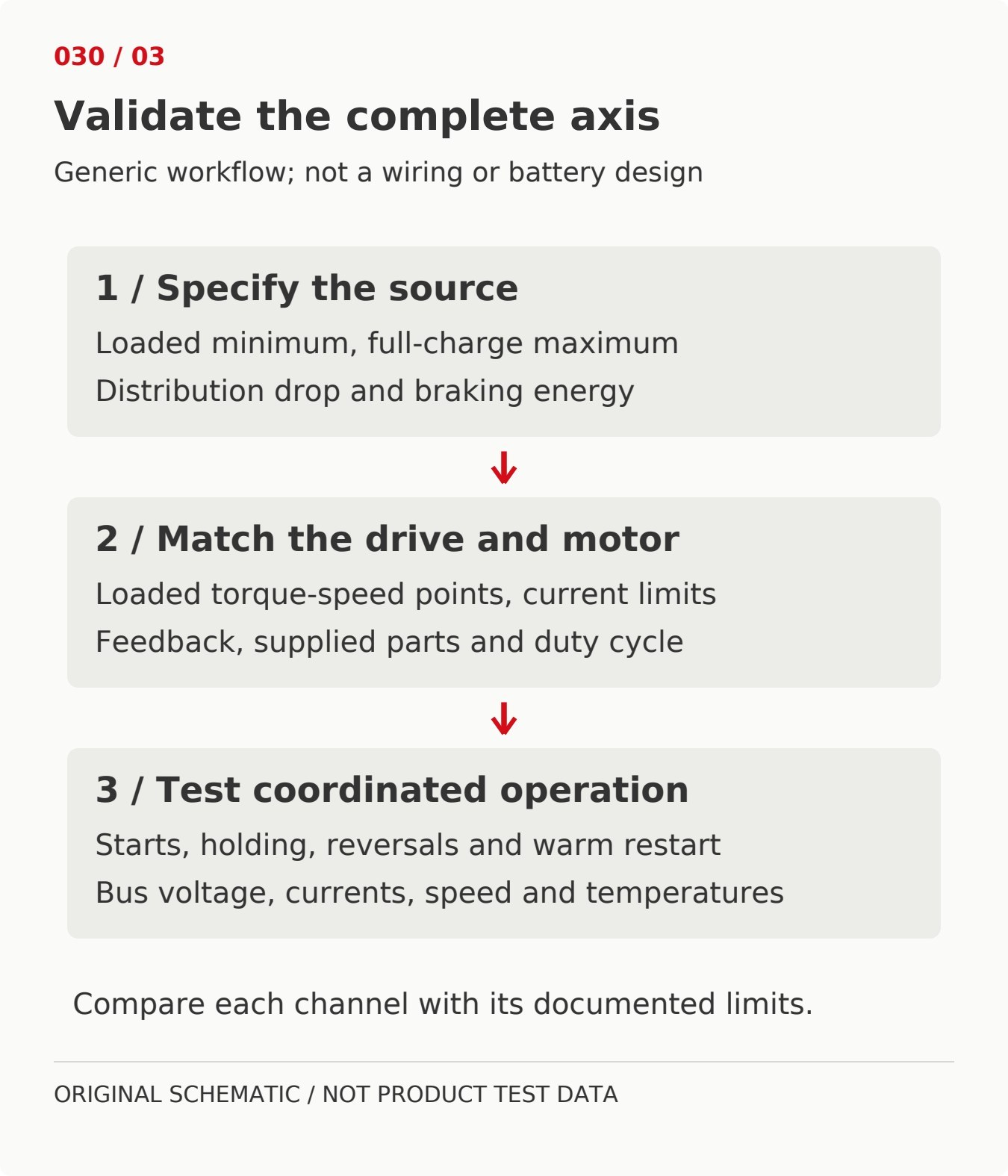
Run the real cycle with coordinated axes, payload, enclosure and representative supply extremes. Record DC-bus voltage at the drive, source current, available phase-current telemetry, speed and component temperatures. Include starts, long holds, reversals, braking and warm restarts. The guide to robot joint motor heat and repeated-duty validation explains the thermal checks that remain necessary even when voltage compatibility looks correct.
6. Read a SolisMotor voltage range without assuming a performance curve
The current MG6010-8 robot joint actuator specifications list a voltage range of 12–48 VDC, rated torque of 5.00 N·m, peak torque of 11.00 N·m and an 8:1 planetary reduction. These fields were checked on October 27, 2026.
The listed voltage range does not state that rated torque, maximum speed and peak capability are simultaneously available across the entire range. Before selecting it for a particular DC bus, request configuration-specific torque-speed curves at your minimum and maximum operating voltages, continuous and peak current definitions, permitted peak duration and the applicable thermal conditions. Also confirm braking-energy behavior and whether feedback and drive electronics are included in the offered configuration.
The SolisMotor motor development and system integration workflow is the appropriate context for that review. Provide the loaded voltage range and motion cycle together, rather than asking only whether a model is a “24 V motor.”
FAQ
Can I select a robot motor using nominal battery voltage alone?
No. Check the lowest voltage at the drive under load, the highest normal voltage, transients and returned braking energy. Then verify the required torque-speed points and drive compatibility throughout those conditions.
Does a 12–48 VDC range mean identical performance at every voltage?
No. An allowed supply range is not a torque-speed map. Obtain the applicable curves, current limits and thermal conditions for the intended drive and configuration.
Does lower supply voltage mean lower motor current?
Not necessarily. At the same achievable mechanical operating point and efficiency, lower bus voltage requires more average DC input current. Motor phase current follows its own torque and drive relationships and must be checked separately.
Is the lowest-KV motor always best for a battery-powered joint?
No. Compare loaded speed, torque per amp, winding resistance, available voltage, drive limits and thermal behavior. A winding that helps one constraint can make another harder to meet.
For a low-voltage robot motor review, send the source's full-charge maximum and loaded minimum, torque-speed cycle, simultaneous-axis demand, mounting drawing and available bus measurements through contact SolisMotor about low-voltage robot motor selection.