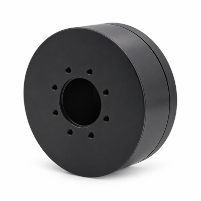
MG3505-8
 MG3505-9
 MG3505-36
 MG4315-8
 MG6010-6
 MG6010-8
 MG4305-10
 MG4310-10
 MG4310-36
 MG4310-40
 MG3510-8
 MG3510-64
 MG6010-36
 MG6010-48
 MG8108-6
 MG8108-8
 MG8108-36
 MG8108-48
 MG8115-6
 MG8115-9
 MG8115-36
 T-4024
 T-4929
 T-6034
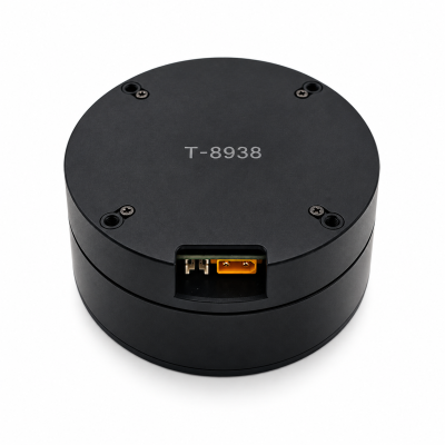
 T-8938
How to Reduce Motor Heat in Compact Robot Joints
Direct answer. Reduce motor heat in compact robot joints by lowering avoidable current, improving the heat path into the mounting structure, and matching the repeated duty cycle to validated thermal limits. Log current, speed, ambient temperature and sensor location before changing hardware. Check winding, housing, drive and gearbox limits separately; a cool outer case or a large peak torque rating does not establish safe continuous operation.
Robot motor overheating is an integration problem as well as a motor-selection problem. Start with the actual enclosure and motion cycle, then compare options in the SolisMotor robot joint motor range. A catalog rating becomes useful only when its mounting, cooling and operating conditions match the proposed joint.
1. Find the heat source before adding cooling
A joint contains several potential heat sources: winding resistance, magnetic losses, bearings, transmission friction and nearby drive electronics. Temperature at one point does not identify which source dominates. Record when the problem appears: static holding, repeated accelerations, sustained speed, or operation after the surrounding structure has warmed up.
At a stationary output, mechanical power is zero even when holding torque requires current. Reducing motion speed alone may therefore leave substantial winding heating. Conversely, the heat load during faster movement can include losses that a holding test misses. The guide to motor efficiency and robot-joint loss boundaries explains why a single efficiency figure cannot describe the whole cycle.
| Observation | What to check first | Evidence to collect before changing the design |
|---|---|---|
| Heating during a long hold | Gravity load, current magnitude, oscillation and friction | Holding posture, phase-current records and stationary temperature trace |
| Heating after repeated moves | Acceleration demand, burst repetition and incomplete cooling | Complete motion cycle, current history and temperatures across successive cycles |
| Heating mainly at sustained speed | Speed-dependent losses and transmission load | Torque, speed, input power and temperature at the same operating point |
| Housing seems moderate but protection trips | Sensor position, sensor identity and internal temperature gradients | Which component triggered, sensor location, protection thresholds and diagnostic record |
| Bench test passes; enclosed joint runs hot | Changed mounting, local ambient and heat from adjacent components | Installed enclosure, bracket contact, neighboring heat sources and local ambient trace |
Scroll within the table to read every column.
This table is a diagnostic starting point, not a fault diagnosis for a particular product. If a protection limit is reached, use the specified protective response; do not raise the limit to keep the test running.
2. Use current correctly when estimating winding heat
For a simplified balanced three-phase winding model with equal phase resistances and equal phase RMS currents:
P_cu = 3 × I_phase,rms² × R_phase
Here, current is the RMS current in each winding branch and resistance is that branch's resistance at the temperature being evaluated. Do not substitute DC-bus current, peak current, a controller's q-axis value, or a line-to-line resistance without checking its definition and conversion. For an unbalanced case, calculate and add the three branch losses separately.
Simon Kalouche's Carnegie Mellon thesis, CMU-RI-TR-16-39 (October 2016), discusses three-phase winding heating and thermal limitations in legged-robot actuators. The square-law relationship helps explain why repeated current peaks matter; it is not a complete temperature model.
Assumed example: why average current alone can underestimate heating
Assume a 10-second repeating cycle with a balanced phase-RMS current envelope of 6 A for 2 seconds and 2 A for 8 seconds. Assume each phase resistance stays at 0.20 Ω throughout. These are invented teaching inputs, unrelated to any SolisMotor model.
I_cycle,rms = √[(6² × 2 + 2² × 8) / 10] = √10.4 ≈ 3.22 A
Average copper loss = 3 × 0.20 × 10.4 = 6.24 W
The arithmetic average of the current envelope is 2.8 A. Squaring that average would predict 4.70 W and underestimate this example's copper loss. Reducing the high-current interval to 4 A, while keeping the same durations and 2 A background, gives 3.84 W. That requires a real reduction in torque demand or another justified design change; lowering a current limit alone may prevent the robot from completing its task.
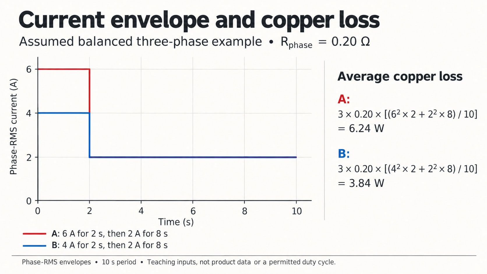
This calculation excludes changing resistance, magnetic, mechanical and drive losses. An RMS screen also omits the order and duration of thermal transients. Check continuous torque versus peak torque and duty limits before treating any repeated burst as acceptable.
3. Improve the whole robot-joint heat path
Heat must travel from internal sources to a surface that can release it. Inspect the stator-to-housing interface, the specified housing-to-bracket mounting surfaces, the bracket and the surrounding air or approved cooling circuit. A larger external heat sink cannot fix every poor internal interface.
Use the specified fit, contact area, fasteners and assembly procedure. Introduce a thermal interface material only when its electrical isolation, thickness, compatibility and effect on tolerances have been checked. Do not fill clearances, block a rotating part, or bypass the product's sealing requirements. A protective shell may reduce exposure to moving parts while also restricting heat rejection; evaluate both functions together. For whole-body packaging context, the SolisMotor humanoid robot joint drive solutions identify the application scope; confirm the actual heat path for each selected joint.
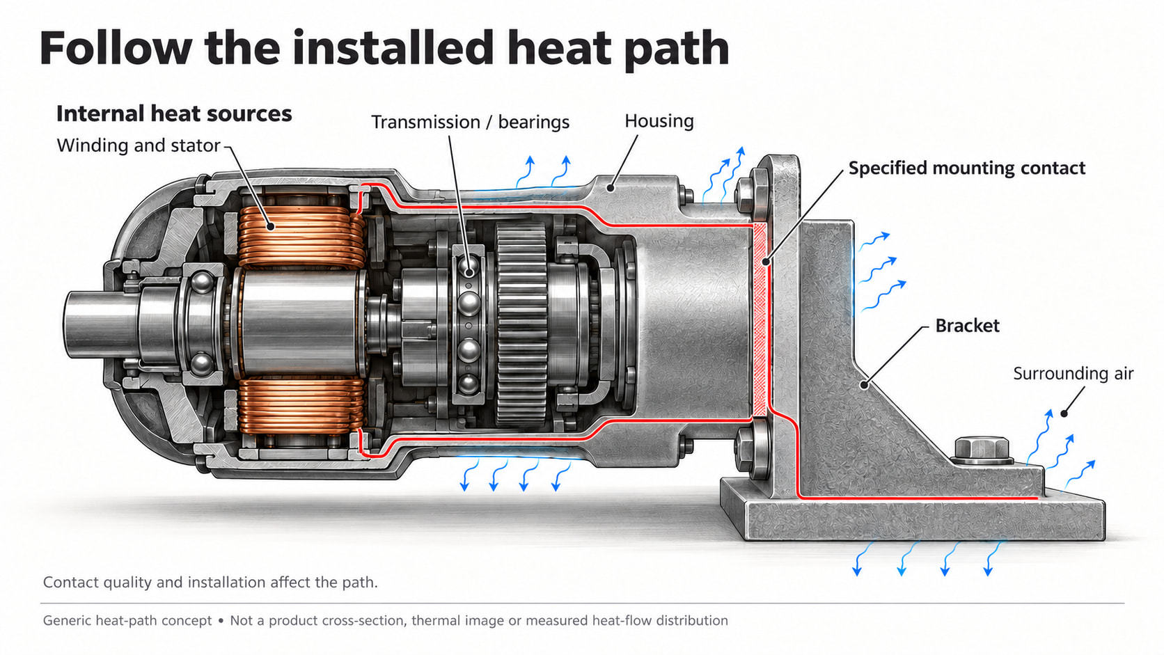
For one simplified steady-state thermal path, temperature rise = heat loss × thermal resistance. Holding total loss at an assumed 6 W, a path of 5 K/W gives a 30 K rise; 3 K/W gives an 18 K rise. These are illustrative values, not measured motor temperatures, permitted winding limits or a cooling-performance promise. Transient behavior and multiple heat sources require a more complete model.
4. Reduce avoidable torque demand and verify the controls
Before selecting a larger motor, inspect mechanical binding, bearing alignment, cable drag and unnecessary holding load. Review motion profiles and control tuning for repeated oscillation or unnecessary current. Counterbalancing or changing the mechanism can reduce gravity-related torque, but introduces mechanical and control requirements of its own.
Changing the reduction ratio affects motor speed, current demand, transmission loss and output behavior together. Use the complete selection workflow in robot joint module versus servo motor selection before assuming a different architecture will run cooler. Raising supply voltage by itself is not a demonstrated remedy for winding heat at unchanged torque and current.
5. Validate temperatures in the final installation
Log synchronized current, output demand, motor speed, local ambient and available component-temperature readings. Label every sensor: a drive-board temperature, housing sensor and winding estimate are different measurements. Check calibration, sample interval, mounting location and the response when communication or a sensor fails.
The University of Tokyo-led research on robot motor core-temperature estimation (external source), available as arXiv:2407.08055v1 (July 10, 2024), models the core, housing and ambient separately. It supports treating housing temperature and internal temperature as different quantities; its parameters and experimental results are not SolisMotor product data.
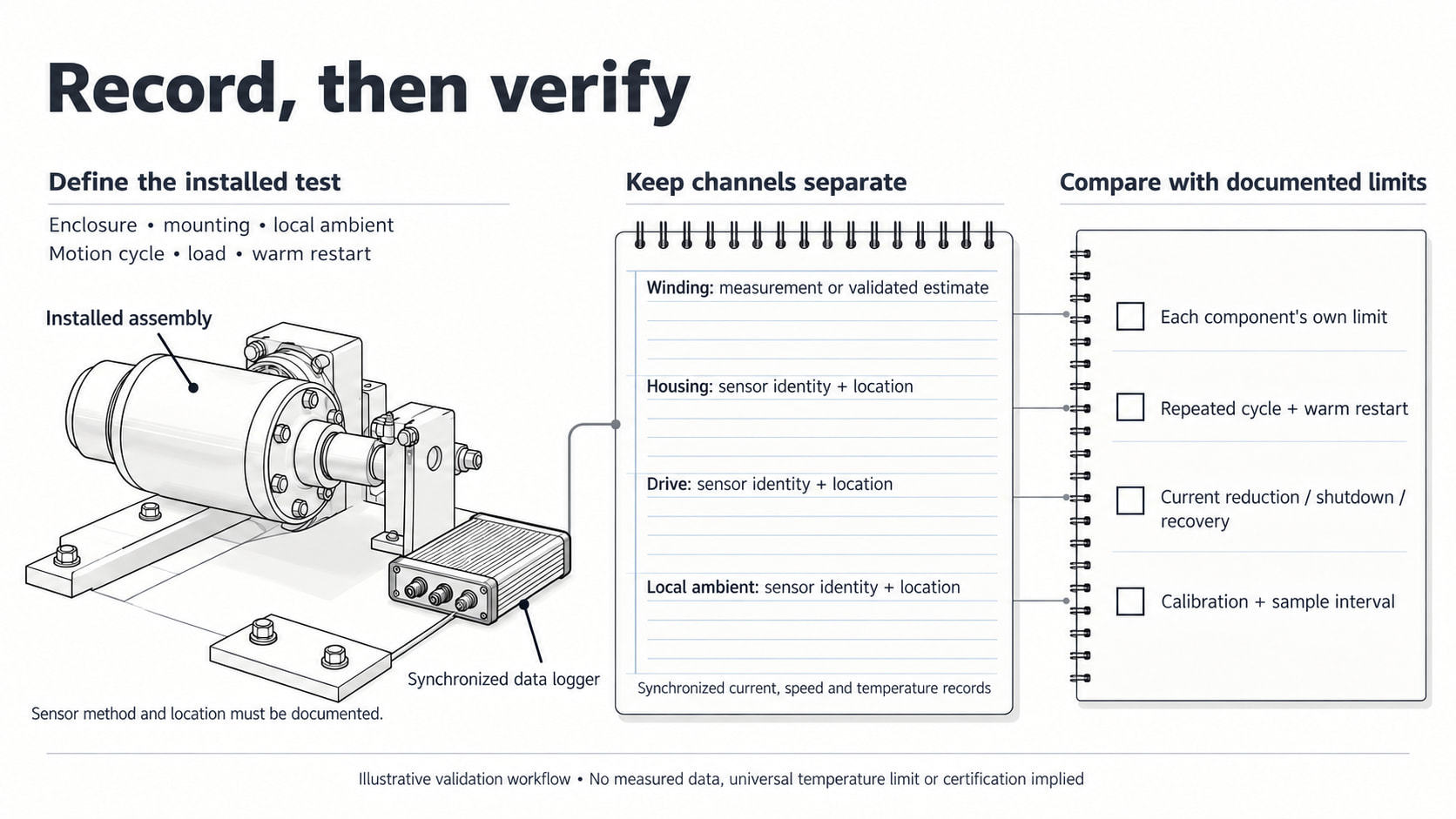
Repeat the intended cycle in the assembled joint, including the specified enclosure, nearby heat sources and relevant worst-case ambient conditions. Continue for a justified mission duration or until repeatable thermal behavior is established under the test protocol. Include restart after a warm pause. Compare each component with its own documented limits and verify current reduction, shutdown and recovery behavior. Do not infer a safe winding temperature from touch or a short open-bench demonstration.
6. Ask for thermal conditions alongside SolisMotor specifications
The current MG6010-8 robot joint actuator specifications list 5.00 N·m rated torque, 11.00 N·m peak torque and an 8:1 planetary reduction. Those fields do not establish the allowable temperature or duty cycle of your enclosed installation.
| Published or required item | What can be used now | What to confirm for the application |
|---|---|---|
| Rated torque | Published MG6010-8 value: 5.00 N·m | Associated speed, ambient, mounting, cooling and operating duration |
| Peak torque | Published MG6010-8 value: 11.00 N·m | Allowed burst duration, repetition, current and speed conditions |
| Reduction | Published MG6010-8 value: 8:1 planetary | Loss behavior at the intended operating points and gearbox limits |
| Temperature protection | No model-specific value is asserted here | Available sensors, their locations, component limits and protection behavior |
| Installed cooling | No thermal resistance or derating curve is asserted here | Applicable mounting interface, enclosure conditions and supporting test evidence |
Scroll within the table to read every column.
The three published product fields were checked on October 26, 2026. For a configuration discussion, the SolisMotor motor development and integration workflow provides the relevant service context. Supply the motion cycle and installed heat path with the inquiry, rather than requesting a generic “cooler motor.”
FAQ
Why does a robot joint motor heat up while stationary?
Holding a load can require current even at zero output speed. Winding resistance then produces heat although output mechanical power is zero. Check the holding torque, current, duty duration and installed cooling conditions.
Does a heat sink always solve robot motor overheating?
No. It can help only when there is an effective path from the hot component to the heat sink and then to the environment. Excess current, an unsuitable duty cycle or another component's limit may remain the constraint.
Is housing temperature enough to protect the winding?
Not by itself. Internal gradients and thermal delay can make the winding hotter than the measured case. Use the product's documented sensing or validated estimation method, with its specified protection settings.
Can RMS current prove the joint is thermally safe?
No. It is a useful screening quantity under stated electrical assumptions. Temperature also depends on other losses, mounting, ambient, time history and component limits. Validate the final assembly and its protection response.
To discuss robot-joint thermal management, send the load and motion cycle, current definitions, local ambient range, mounting drawing and available temperature logs through contact SolisMotor about robot joint motor selection.