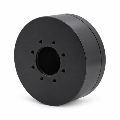
MG3505-8
 MG3505-9
 MG3505-36
 MG4315-8
 MG6010-6
 MG6010-8
 MG4305-10
 MG4310-10
 MG4310-36
 MG4310-40
 MG3510-8
 MG3510-64
 MG6010-36
 MG6010-48
 MG8108-6
 MG8108-8
 MG8108-36
 MG8108-48
 MG8115-6
 MG8115-9
 MG8115-36
 T-4024
 T-4929
 T-6034
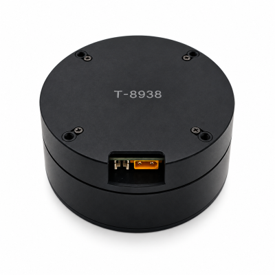
 T-8938
How to Calculate Motor Power for a Robot Joint
SOLISMOTOR · TECHNICAL GUIDES
Calculate robot-joint mechanical power with P = T × ω, using torque and speed measured at the same shaft and at the same instant. With torque in N·m and speed in rpm, P [W] = T × n × 2π/60. Then account for transmission, motor and drive losses to estimate electrical input. Retain the sign of power through braking, and check holding current separately at zero speed.
A joint's wattage alone cannot establish whether it can lift, hold or accelerate your load. This guide turns an existing torque–speed profile into a power and energy budget. If you still need that profile, use the motor torque and speed calculation guide first.
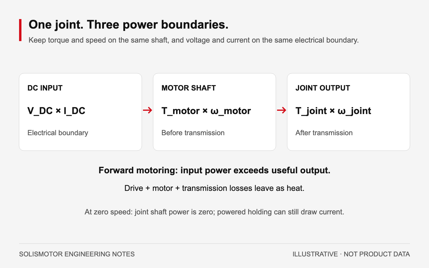
1. Name the power boundary before calculating
A robot joint has several power boundaries. The following quantities can all be expressed in watts, but they answer different questions.
Swipe the table horizontally to view all columns.
| Boundary | Quantity | What it helps you assess |
|---|---|---|
| Joint output shaft | P_joint = T_joint × ω_joint | Mechanical power delivered to or absorbed from the link |
| Motor shaft | P_motor = T_motor × ω_motor | Mechanical requirement at the transmission input |
| Drive DC input | P_DC = V_DC × I_DC | Electrical power drawn from or returned to the DC bus |
| Robot supply or battery | Sum of simultaneous bus loads plus distribution and auxiliary loads | System demand and energy use |
Use positive DC current for power entering the drive. During regeneration, negative current means the drive sends power back to the bus. Measure voltage and current at the same electrical boundary; motor phase current is not DC supply current.
For rapidly varying signals, average the instantaneous product V(t)I(t) over the relevant interval. Multiplying two separately averaged signals can give a different result. Record the sensor bandwidth and sampling rate when checking short power pulses.
2. Calculate signed mechanical power along the motion
Convert rpm to angular speed using ω = 2πn/60. If the joint requires 12 N·m while turning at 30 rpm:
P_joint = 12 × 30 × 2π/60 = 37.70 W
This is mechanical output at that operating point. The 12 N·m and 30 rpm must occur together. Multiplying the highest torque in one part of a cycle by the highest speed in another can overstate its actual maximum power.
Keep a consistent positive rotation direction. Torque and speed with the same sign give positive mechanical power. Opposite signs give negative mechanical power: the mechanism is driving the actuator. A lowering load can therefore return energy even while the joint continues moving in its commanded direction.
At zero speed, T × ω = 0 W, including when the motor holds a nonzero load. The motor can still draw current and dissipate heat. MIT's actuator and drive-system notes (external source) develop the electromechanical power relation and winding-resistance loss. For a three-phase motor, calculate copper loss from the actual phase currents and winding resistances, with their stated current convention; do not substitute DC bus current into a phase-loss formula.
3. Carry power through the gearbox and electrical drive
Define a reduction ratio as G = n_motor/n_joint, with G greater than 1. At a steady forward-motoring point, using gearbox efficiency η_g:
n_motor = G × n_joint
T_motor = T_joint/(G × η_g)
P_motor = P_joint/η_g
The ratio changes torque and speed; it does not multiply available power. Northwestern University's Modern Robotics discussion of gearing and friction (external source) explains ideal power preservation and real transmission losses. The direct-drive and harmonic-drive comparison gives context for choosing a joint architecture.
For positive mechanical output, a first estimate of drive input is:
P_DC ≈ P_motor/(η_motor × η_drive)
This estimate requires efficiencies applicable to that speed, torque, voltage and temperature. Confirm whether a published efficiency includes the drive or gearbox before multiplying factors. The US Department of Energy's motor and drive-system sourcebook (external source) defines efficiency as useful output divided by input and describes motor-system losses. Its industrial-motor data are not efficiency values for a particular robot joint.
Constant efficiencies are unsuitable at zero speed and can be poor approximations at light load. Use a loss map or measured input instead. During rapid transients, also account for changing stored mechanical and magnetic energy within the chosen boundary. Do not apply the forward-motoring formula unchanged to regeneration; reverse transmission losses and electrical recovery need their own model.
4. Worked example: output power to DC demand
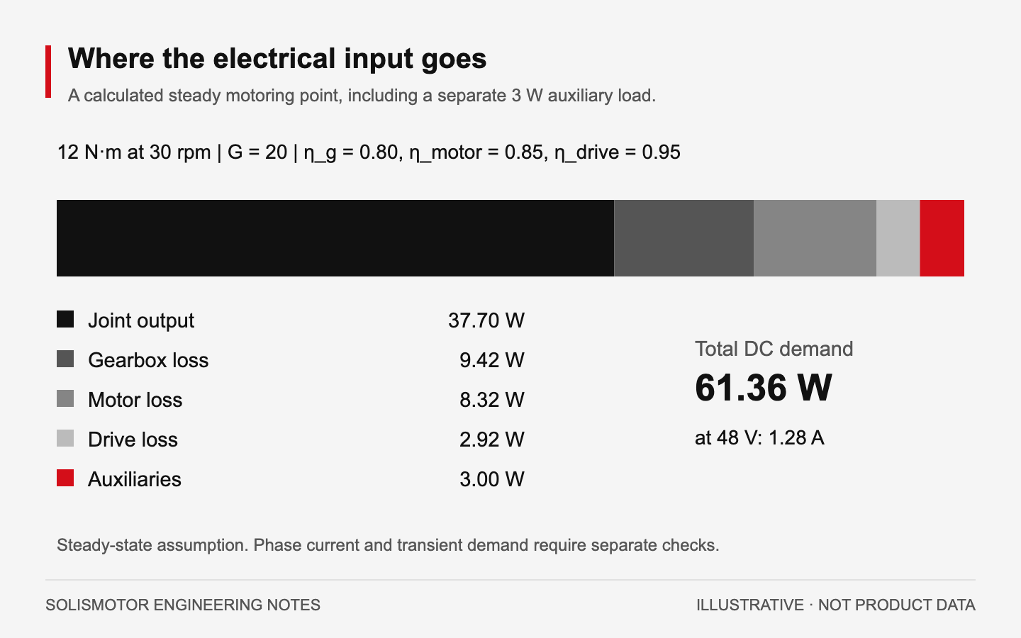
The following is a hypothetical steady motoring point, not a SolisMotor product specification. It excludes acceleration, changing internal stored energy and transient bus behavior. Auxiliary power is a separate load on the same DC supply, outside the assumed motor and drive efficiencies.
Swipe the table horizontally to view all columns.
| Assumption | Value |
|---|---|
| Joint output torque and speed | 12 N·m at 30 rpm |
| Reduction ratio G | 20:1 |
| Gearbox efficiency η_g | 0.80 |
| Motor efficiency η_motor | 0.85 |
| Drive efficiency η_drive | 0.95 |
| Separate auxiliary demand | 3.00 W |
| DC supply voltage | 48 V |
The motor turns at 600 rpm and supplies 0.75 N·m at the gearbox input. The corresponding power budget is:
Swipe the table horizontally to view all columns.
| Calculation | Result |
|---|---|
| Joint mechanical output | 37.70 W |
| Motor mechanical output: 37.699/0.80 | 47.12 W |
| Motor electrical input: 47.124/0.85 | 55.44 W |
| Drive DC input: 55.440/0.95 | 58.36 W |
| Total DC demand including auxiliaries | 61.36 W |
| DC supply current: 61.358/48 | 1.28 A |
Calculate with unrounded values, then round the results. The difference between 61.36 W entering the modeled system and 37.70 W at the joint output is 23.66 W of combined loss and auxiliary demand. The motor's share is about 8.32 W; the remainder occurs elsewhere. Do not assign every system loss to motor heating.
The estimated 1.28 A is supply current at this steady point. It does not specify motor phase current, acceleration current or the required power-supply transient rating.
5. Integrate a cycle for energy, then check power peaks
Energy is power accumulated over time: E = ∫P(t)dt. For constant-power intervals, use E = ΣP_i × Δt_i. Joules become watt-hours by dividing by 3,600.
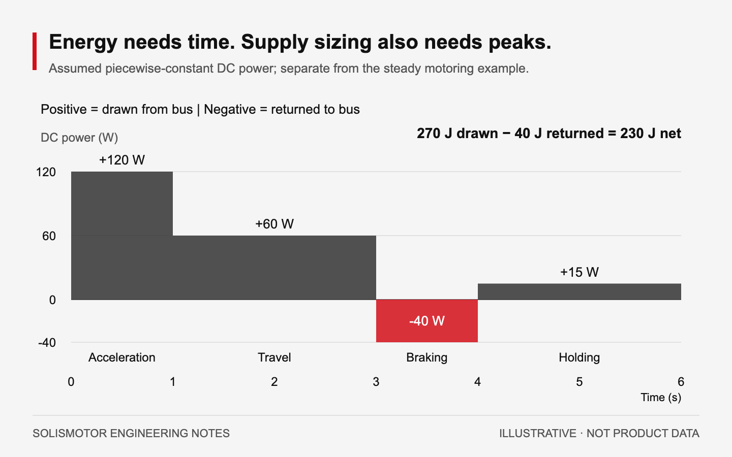
Consider a separate illustrative DC-boundary trace. These assumed piecewise-constant values already include the loads assigned to that measurement boundary. They are not derived from the steady example above and are not measured robot data.
Swipe the table horizontally to view all columns.
| Interval | Duration | Signed DC power | Energy |
|---|---|---|---|
| Acceleration interval | 1 s | +120 W | +120 J |
| Travel interval | 2 s | +60 W | +120 J |
| Regenerative braking interval | 1 s | −40 W | −40 J |
| Powered holding interval | 2 s | +15 W | +30 J |
Positive energy demand totals 270 J; energy returned across this boundary is 40 J. If the bus accepts and retains or reuses that return, net energy is 230 J, or 0.0639 Wh per six-second cycle. Average net power is 38.33 W. The highest positive power in this assumed trace is 120 W. An average-power number therefore cannot size the supply's peak response. Real waveforms may contain higher, shorter pulses than these illustrative intervals.
Motor thermal loading needs a separate check. Average signed mechanical power can approach zero over a repeated move while copper losses remain positive during both acceleration and braking. Evaluate phase-current RMS, temperature and continuous/peak torque limits under the specified cooling conditions. The robot-joint torque, heat and integration guide provides the system context.
6. Give regenerated energy somewhere to go
Negative mechanical power indicates energy absorption at the shaft; electrical losses can consume some or all of it before it reaches the DC bus. When a drive does return energy, the receiving system must accommodate it. Possible destinations include another motoring axis, an accepting battery or storage device, a regenerative supply, or a correctly rated braking circuit.
Khalaf and Richter's research on regenerative robot drives (external source) demonstrates energy storage and recovery on a particular experimental system. It does not establish that a standard power supply or battery will accept returned current.
For an ideal capacitor, the energy headroom between bus voltages V_initial and V_limit is ΔE = ½C(V_limit² − V_initial²). As an illustrative calculation, 2,000 µF between 48 V and 54 V stores only 0.612 J of additional energy. That is much less than the 40 J return in the assumed cycle. This calculation ignores tolerances and transient effects; it is an energy comparison, not a capacitor or braking-circuit design.
Check the actual drive voltage limits, supply reverse-current behavior, battery charge limits and braking hardware. If returned energy is dissipated in a resistor, it can support braking without becoming energy recovered by the source.
7. Prepare a requirement that an engineer can verify
For a SolisMotor configuration review, supply a time-aligned torque and speed trace, identify the reference shaft and describe the transmission. Include holding periods, concurrent axes and representative emergency or abnormal stops where they affect the drive requirement.
State the DC voltage range, estimated positive and returned power, energy per cycle, auxiliary loads and available cooling. Ask for efficiency or loss data at the operating points you use, plus continuous torque, permitted peak duration, phase-current limits and the torque–speed envelope. Compare those requirements with the relevant Robot Joint Motor range and the exact configuration's current drawings and data.
Validate the budget on the assembled axis using synchronized measurements. A calculated wattage is a sizing input; acceptance depends on the required motion, temperature and electrical limits being met together.
FAQ
Can I calculate motor power from torque alone?
Mechanical shaft power also requires speed. At zero speed the shaft power is zero, while holding torque can still require electrical input and cooling.
Does a 20:1 gearbox reduce the required power by twenty?
An ideal reduction trades speed for torque while preserving power. A real gearbox adds losses. The worked example needs 47.12 W at the motor shaft to deliver 37.70 W at the joint output with an assumed 0.80 efficiency.
Is DC bus current the same as motor phase current?
They refer to different parts of the drive. Use DC voltage and DC current to evaluate bus power, and the specified phase-current convention to check motor torque and winding heating.
Can I subtract braking energy when sizing a power supply?
Use returned energy in a net-energy budget only when the receiving system can accept it. Supply sizing must also cover positive power pulses, voltage behavior and the treatment of returned energy.