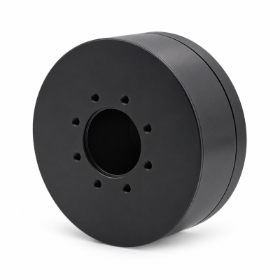
MG3505-8
 MG3505-9
 MG3505-36
 MG4315-8
 MG6010-6
 MG6010-8
 MG4305-10
 MG4310-10
 MG4310-36
 MG4310-40
 MG3510-8
 MG3510-64
 MG6010-36
 MG6010-48
 MG8108-6
 MG8108-8
 MG8108-36
 MG8108-48
 MG8115-6
 MG8115-9
 MG8115-36
 T-4024
 T-4929
 T-6034
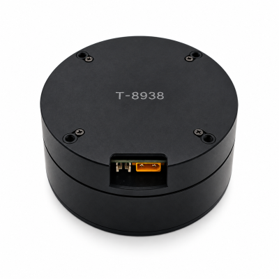
 T-8938
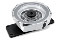
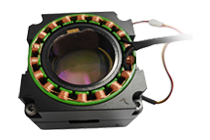
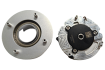
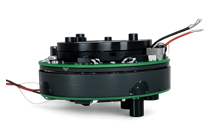
How to Select a BLDC Motor for a Robotic Arm
Select a BLDC motor for a robotic arm from the complete per-axis load and motion cycle. Include the links, tool, payload and moving cables. Evaluate the planned poses and accelerations, then compare the motor, reduction, drive and feedback under the same installed conditions. Payload in kilograms alone does not define a joint motor.
Begin with the SolisMotor Robot Joint Motor range to identify possible assembly types. Before requesting a model recommendation, prepare the arm geometry, mounting orientation and time-based operating requirements described below.
Define the arm and the task before choosing a motor
Record the joint axes, link masses and centers of mass, tool and payload mass properties, mounting direction and intended working poses. Include gripper hardware, hoses and dress cables. Identify which parts move with each axis and which are supported elsewhere.
Build a trajectory with position, velocity, acceleration, dwell time and repetition. A horizontal reach-and-hold task differs from a vertical lift or a short transfer, even when the payload is identical. Check each axis through the complete intended path.
For an end-effector load, the Jacobian-transpose relationship maps the combined force and moment to joint loads. Use consistent coordinates and signs. Link gravity and motion-dependent loads must also be included. These are separate contributions, not interchangeable estimates. Technical basis: Lynch and Park, Modern Robotics, section 5.2; Tedrake, Underactuated Robotics, Multi-Body Dynamics.
Diagram: swipe horizontally on small screens.
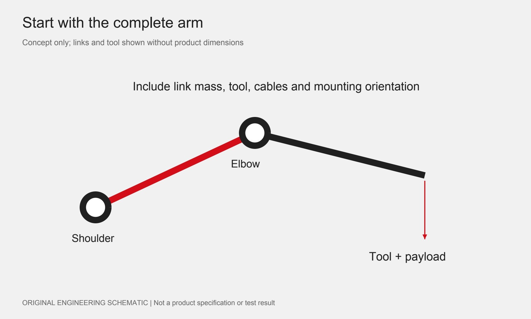
A static shoulder-load example: include more than the payload
Assume a planar arm is stationary and horizontal. Assume the center of mass of the 2.0 kg tool-plus-payload is 0.40 m horizontally from the shoulder axis. Represent the links by an equivalent 1.0 kg mass with its center of mass 0.20 m horizontally from that axis. Take g = 9.81 m/s². Ignoring every other load for this teaching example, the gravity torque magnitude is:
τ = 2.0 × 9.81 × 0.40 + 1.0 × 9.81 × 0.20 = 9.81 N·m.
The tool-plus-payload contributes 7.848 N·m; the assumed link contributes another 1.962 N·m. Selecting from the first value alone would omit a real category of load. For these assumed masses aligned together at an angle θ from horizontal, the gravity term scales with cos θ; at 60 degrees its magnitude is 4.905 N·m.
This is not a motor rating or a complete dynamic sizing result. A real arm has multiple moving links, changing geometry, friction and cable forces. Acceleration and interactions between axes require a complete model. Do not combine the maximum torque from one pose with the maximum speed from another and call it a simultaneous operating point.
Diagram: swipe horizontally on small screens.
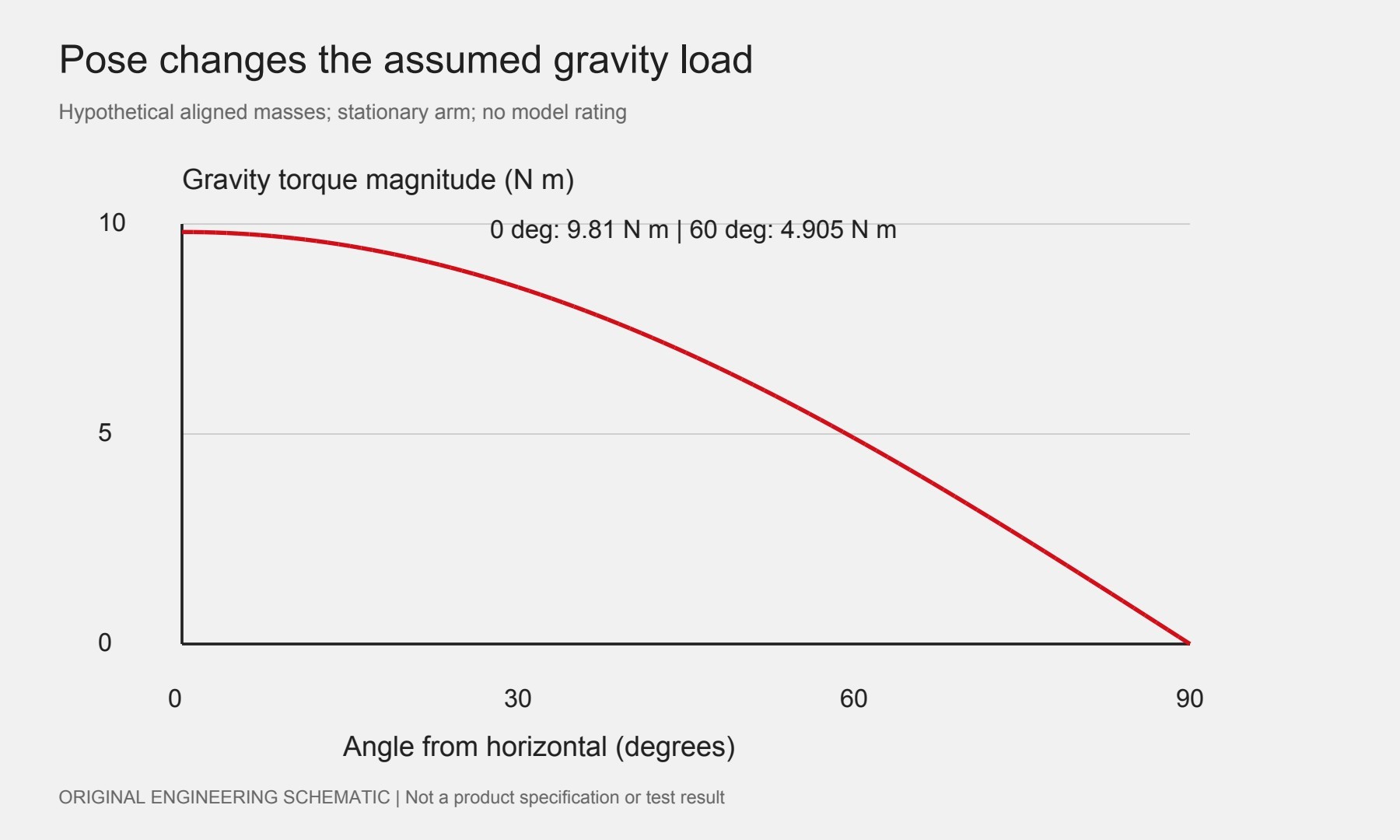
Match the complete axis, including the drive and reduction
Before comparing quotes, specify whether you need a bare motor or an assembled joint. List who supplies the reduction, output bearings, drive electronics, feedback and any holding device. Confirm the included parts and installed mass for each candidate so that a smaller delivery scope is not mistaken for a more compact complete solution.
Keep joint-output and motor-shaft quantities separate. With reduction N defined as motor speed divided by joint speed, motor speed is N times joint speed. An ideal torque conversion is only a starting calculation; use confirmed transmission losses, operating direction and limits for the actual assembly. Review the continuous and peak torque conditions before comparing candidates.
Table: swipe horizontally to see all three columns.
| Requirement | Specify | Check |
|---|---|---|
| Motion duty | Joint-output torque (N·m) and speed (rpm) versus time (s) | Peak duration, repeated cycle and dwell |
| Electrical supply | Loaded DC bus (V) and current limits (A) | Motor/drive compatibility; phase vs DC-bus current definitions; braking conditions |
| Mechanics | Output support loads and installed interfaces | Bearing capacity, stiffness, lost motion and cable travel |
| Feedback | Required output position behavior | Sensor location, startup reference and complete-axis error |
A motor encoder alone does not describe output accuracy through a transmission. The robot joint encoder selection guide explains useful feedback questions. A stationary arm can still require torque and produce heat; review the installed joint heat path when evaluating long holds.
Verify the installed arm before approving the motor and drive
Test the agreed cycle with representative links, tool, payload, cable routing and cooling. Retain synchronized motion and electrical records, temperature measurements, positioning results and the conditions of each test. Treat untested poses or load combinations as unverified.
Agree the acceptance criteria before testing. For each criterion, record the limit, measured result, test conditions and status: passed, failed or not tested. A no-load test does not establish performance over the full payload cycle.
Assess power-loss holding and stopping separately through the machine risk assessment. A BLDC motor is not inherently a fail-safe holding brake. Specify what the mechanism must do after power loss; this article does not define a complete robot safety design.
Diagram: swipe horizontally on small screens.
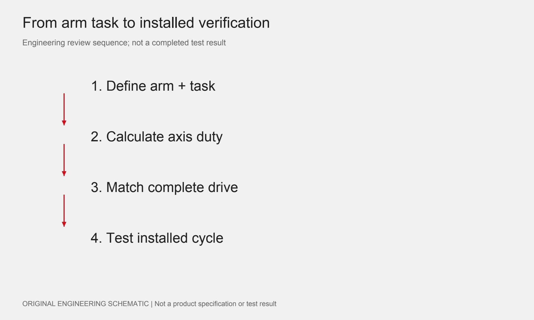
Use the SolisMotor engineering-services overview for the project discussion, and submit the geometry, trajectory, load assumptions and acceptance criteria through the SolisMotor contact page. Ask for confirmed candidate drawings and operating limits. No model is qualified by the hypothetical example above.
Frequently asked questions
Can one motor type serve every arm joint?
Only if the complete assembly meets every relevant axis requirement. Shoulder, elbow and wrist loads must be evaluated separately.
Can payload mass and reach determine the motor?
No. For a planar joint, a static gravity-torque magnitude is mass × gravitational acceleration × the perpendicular distance from the pivot to the gravity force’s line of action. This gravity moment arm is not automatically the link length. Include the tool and links, then evaluate the full motion cycle. Technical basis: OpenStax, University Physics Volume 1, section 10.6.
Does zero speed mean zero heating?
No. Holding torque can require current at zero speed. Verify the actual holding duty and thermal conditions.