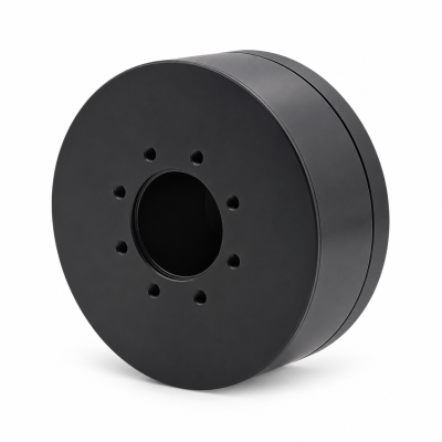
MG3505-8
 MG3505-9
 MG3505-36
 MG4315-8
 MG6010-6
 MG6010-8
 MG4305-10
 MG4310-10
 MG4310-36
 MG4310-40
 MG3510-8
 MG3510-64
 MG6010-36
 MG6010-48
 MG8108-6
 MG8108-8
 MG8108-36
 MG8108-48
 MG8115-6
 MG8115-9
 MG8115-36
 T-4024
 T-4929
 T-6034
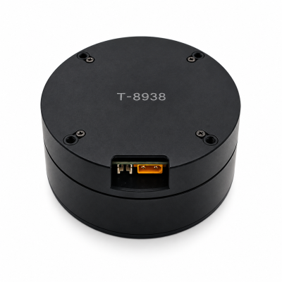
 T-8938
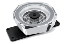
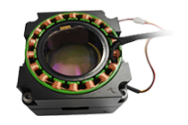
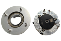
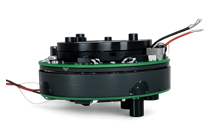
How to Design a Compact High-Torque Robot Joint
Direct answer. Design a compact high-torque robot joint around the installed load path and available space. Define torque, speed, external forces and bending moments first. Then package the motor, transmission, support bearings, feedback, cables and heat path together. Verify the assembled joint through its motion and duty cycle; a small motor envelope or high peak torque alone cannot establish a workable design.
Start with the SolisMotor Robot Joint Motor range to identify candidate hardware. Use the steps below to connect output loads with a joint that can be assembled, wired and tested within its installed envelope.
1. Set the robot joint design requirements
Write one requirements sheet for the output axis: motion range, speed, acceleration, holding periods, repeated loads and exceptional load cases. Locate the load application points and define the coordinate system. Keep installation limits beside these requirements: outside diameter, axial length, mass, mounting interfaces and service access.
Specify output positioning accuracy, repeatability and allowable deflection under a stated load. Define how these will be measured at the assembled output; encoder resolution alone is not an assembly acceptance criterion. State what the joint must do when power is removed, and include any required holding hardware in the space and mass budget.
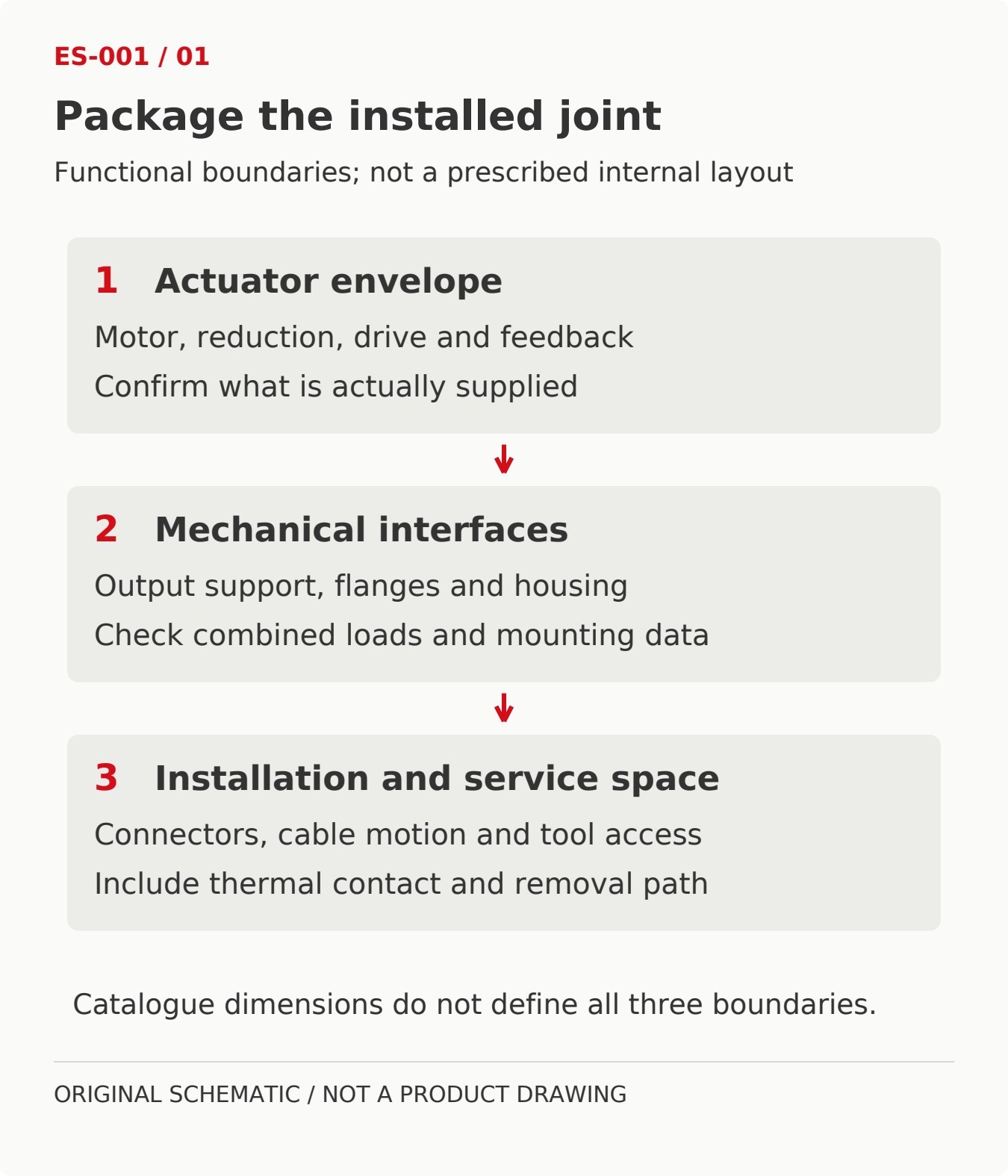
Distinguish the supplied actuator from the finished joint. An integrated unit may include a motor, reduction, drive and feedback, but the robot can still require brackets, link interfaces, cable restraints and additional load support. Confirm the actual delivery configuration using the joint module versus servo motor comparison before assigning integration work.
Use an installed envelope that includes connector mating space, cable movement and tool access. A design that fits in CAD but cannot be wired, tightened or serviced is not yet a usable compact joint.
2. Separate drive torque from bearing-load requirements
For a revolute joint, torque about its rotation axis is only one part of the mechanical demand. Radial and axial forces, plus moments about the other axes, also need a documented path through the output interface, support bearings and housing to the robot structure. A motor's torque rating does not specify those load capacities.
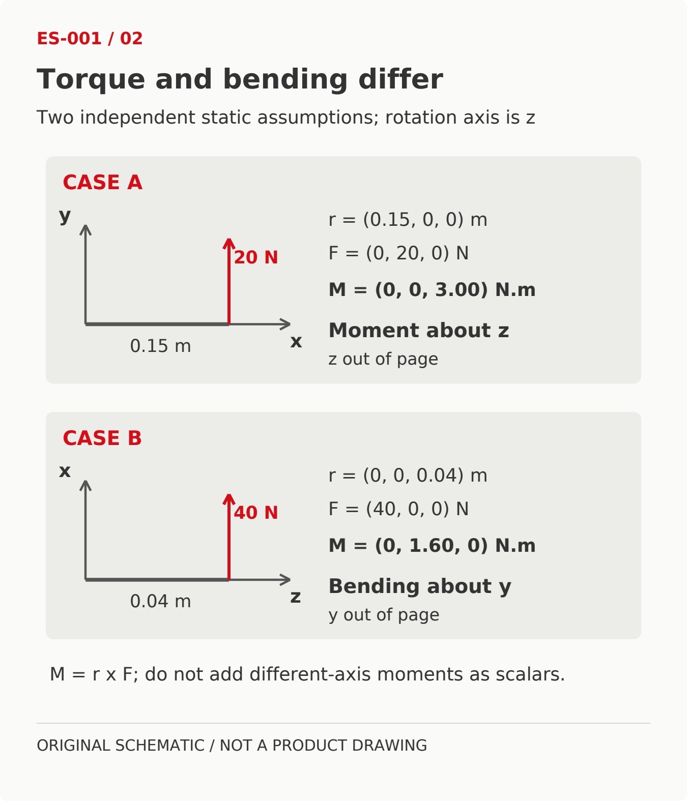
For a force applied at a known point, use the vector relation M = r × F, with both vectors expressed in the same frame. The moment component along the joint axis contributes to the axis torque; perpendicular components are bending moments. The underlying force-and-moment representation is explained in Lynch and Park's Modern Robotics, Section 3.4, hosted by Northwestern University (external source), Cambridge University Press, 2017; updated preprint dated December 30, 2019.
Assumed example: two different load directions
Take the rotation axis as z and the reference origin as a specified point on that axis. These are independent static teaching cases, not SolisMotor test data:
Case A: tangential force
Position: r = (0.15, 0, 0) m
Force: F = (0, 20, 0) N
Moment: M = (0, 0, 3.00) N·m
This force contributes 3.00 N·m about z. The 20 N transverse force must also be included in the support-load analysis.
Case B: offset transverse force
Position: r = (0, 0, 0.04) m
Force: F = (40, 0, 0) N
Moment: M = (0, 1.60, 0) N·m
This force creates 1.60 N·m bending about y and a 40 N transverse force. Its moment about z is zero.
Do not add 3.00 and 1.60 as scalar drive torques. If both forces act together, combine their force and moment vectors at the same reference point. Actual bearing reactions additionally depend on support locations and geometry. Neither case includes link weight, inertia, friction, impact or a complete motion cycle, so neither establishes a motor or bearing selection.
Request permissible combined radial, axial and moment loads for the proposed mounting arrangement, together with life and speed conditions. Confirm whether the actuator's own output support is sufficient or whether the robot needs separate bearings. Do not infer support capacity from gearbox ratio, encoder resolution or the diameter of the housing.
3. Package the motor, gearbox and output support
Develop a simple envelope model before detailing every surface. Show stationary and rotating parts separately, then sweep the complete motion range. Include adjacent links, connector bodies and the moving cable volume, not just the actuator's central cylinder.
Swipe or scroll within the table to read all columns.
| Design area | Evidence to obtain | Packaging decision it supports |
|---|---|---|
| Output support and flanges | Load limits, mounting drawing, bearing arrangement and interface requirements | Where external loads enter the structure; whether extra support is needed |
| Motor and reduction | Torque-speed duty, reduction data and actual assembly dimensions | Diameter versus length trade-offs and achievable output motion |
| Cables and feedback | Connector locations, cable bend limits, feedback configuration and routing instructions | Keep-out zones, strain relief, motion clearance and assembly sequence |
| Output precision and holding | Allowed deflection and lost motion, output test conditions and required power-off behavior | Structural and interface stiffness, feedback placement and any holding-device space |
| Housing and service | Heat-path requirements, interface tolerances and access for specified tools | Wall and interface layout, mounting contact, removal and inspection access |
A larger motor with less reduction and a smaller motor with more reduction are different design candidates. Compare their complete dimensions, losses, output speed, inertia and control behavior under the same duty. A higher reduction ratio does not automatically produce a smaller finished joint. Use the strain-wave versus planetary gearbox selection guide when narrowing the transmission options.
Choose fits, fasteners and bearing preload from the relevant component drawings and mechanical analysis. Do not transfer them from a visually similar unit. Check the assembly order too: a fastener that becomes inaccessible after installing the motor can force a housing redesign.
For a humanoid platform, the SolisMotor humanoid joint-drive solutions page provides application context for discussing the proposed axis and interfaces. It does not replace drawings or load qualification for your assembly.
4. Reserve the thermal and electrical space early
Mechanical compactness must leave room for the drive, connectors and an effective path for heat to leave the installed assembly. Establish the intended mounting contact and enclosure conditions before deciding that a catalogue continuous rating applies to the robot.
Do not treat every unused gap as available for a thicker bracket or another cable. Cable movement, insulation clearance and service access can already occupy that space. Check the proposed cable route at both motion limits and during assembly; use the cable supplier's bend and torsion limits instead of an assumed universal radius.
Keep heat verification tied to the intended duty, including loaded holds and repeated reversals. The compact robot joint heat-reduction guide explains the related thermal checks. Packaging changes that alter the mounting contact or enclosure need renewed thermal evaluation.
5. Check a compact actuator against the installed envelope
The current MG6010-8 shoulder joint actuator specifications list Ø80 × 40 mm, 5.00 N·m rated torque, 11.00 N·m peak torque and an 8:1 planetary reduction. These are published product values, checked on October 28, 2026, rather than results from the assumed load cases above.
Use that envelope as a starting block for an installation study. It does not establish the final width across brackets, cable clearance, combined bearing-load capacity or available torque at every speed. Peak torque also needs its permitted duration, repetition and operating conditions before it can support a duty-cycle decision.
Obtain the controlled drawing, connector arrangement, supplied feedback configuration and applicable load and torque-speed information for the exact unit being evaluated. A public summary should help identify questions for engineering review, not silently answer specifications it does not provide.
6. Validate the installed joint before freezing the design
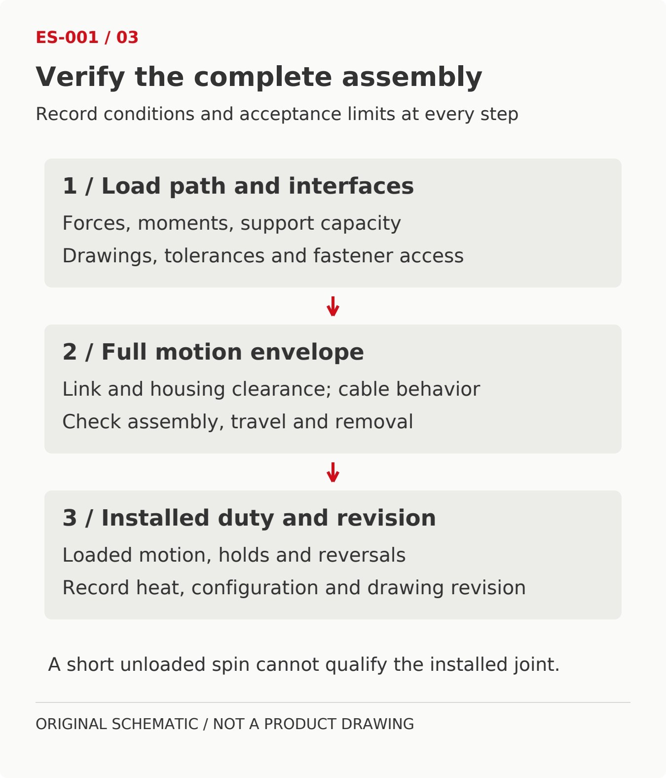
Use an assembly-level review with measurable acceptance criteria. For each requirement, record the condition, evidence and responsible owner. The aim is to find whether a packaging choice has moved a problem into loading, heat, cabling or maintenance.
- Review the load path and interfaces. Resolve combined support loads, mounting surfaces, fastener access and dimensional tolerances with the actual component data and structural analysis.
- Check the complete motion envelope. Inspect link collisions, rotating clearances and cable behavior through travel, including installation and removal. A stationary screenshot cannot establish dynamic clearance.
- Test the intended duty. Evaluate loaded motion, holding and reversals in the intended enclosure and mounting arrangement. Measure output positioning, lost motion and load-induced deflection under the specified conditions, together with relevant temperatures. Verify required power-off behavior separately; a short unloaded spin cannot replace these checks.
- Recheck the representative assembly. Confirm that the drawing revision, actuator configuration, cable route and mounting contact match the tested build. Reassess affected checks when one of those changes.
Bring the load cases, available envelope and interface drawings into the SolisMotor engineering collaboration process. Identify missing limits explicitly so that quotation, design review and sample evaluation refer to the same configuration.
FAQ
Does higher peak torque make a robot joint more compact?
It can expand the candidate list, but it does not prove a smaller installed assembly. Continuous duty, reduction, support loads, cooling, cables and mounting space still have to fit and meet their limits.
Can the actuator's output bearing support the robot link?
Only if the documented load capacity and mounting conditions cover the actual combined forces and moments. Otherwise, evaluate a separate support arrangement. Motor torque alone cannot answer this question.
Does high encoder resolution guarantee a precise, stiff joint?
No. Evaluate the assembled output against its positioning, lost-motion and load-deflection requirements. Specify the load, motion direction and temperature conditions so that candidate assemblies are compared consistently.
What should an OEM provide for a compact joint design review?
Provide the motion cycle, force application points, coordinate system, space and mass limits, interfaces, output precision requirements, environment and cable constraints. Include the required power-off behavior and mark unknowns for review before detailed design.
For a configuration discussion, send your joint envelope and load requirements to SolisMotor with the relevant drawings and duty conditions.