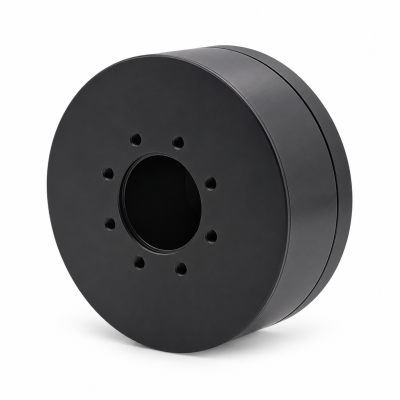
MG3505-8
 MG3505-9
 MG3505-36
 MG4315-8
 MG6010-6
 MG6010-8
 MG4305-10
 MG4310-10
 MG4310-36
 MG4310-40
 MG3510-8
 MG3510-64
 MG6010-36
 MG6010-48
 MG8108-6
 MG8108-8
 MG8108-36
 MG8108-48
 MG8115-6
 MG8115-9
 MG8115-36
 T-4024
 T-4929
 T-6034
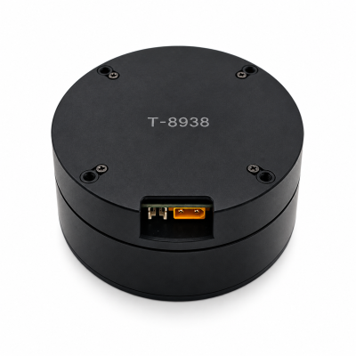
 T-8938
How to Choose a Motor for a Quadruped Robot
To choose a motor for a quadruped robot, calculate each joint’s torque and speed over a complete gait. Account for any transmission, including its losses, then check overload timing, heating and drive limits. Compare feedback and mechanical integration before testing a representative leg. Keep the shortlist provisional until the supplier confirms operating limits and the assembled leg meets its acceptance criteria.
Use the SolisMotor Robot Joint Motor range after defining the load. Read the guide in four steps: model the gait, screen the operating cycle, choose the transmission and feedback, then qualify the leg. The supplier-confirmation table below turns those steps into a practical inquiry sheet.
1. Turn the gait into separate joint requirements
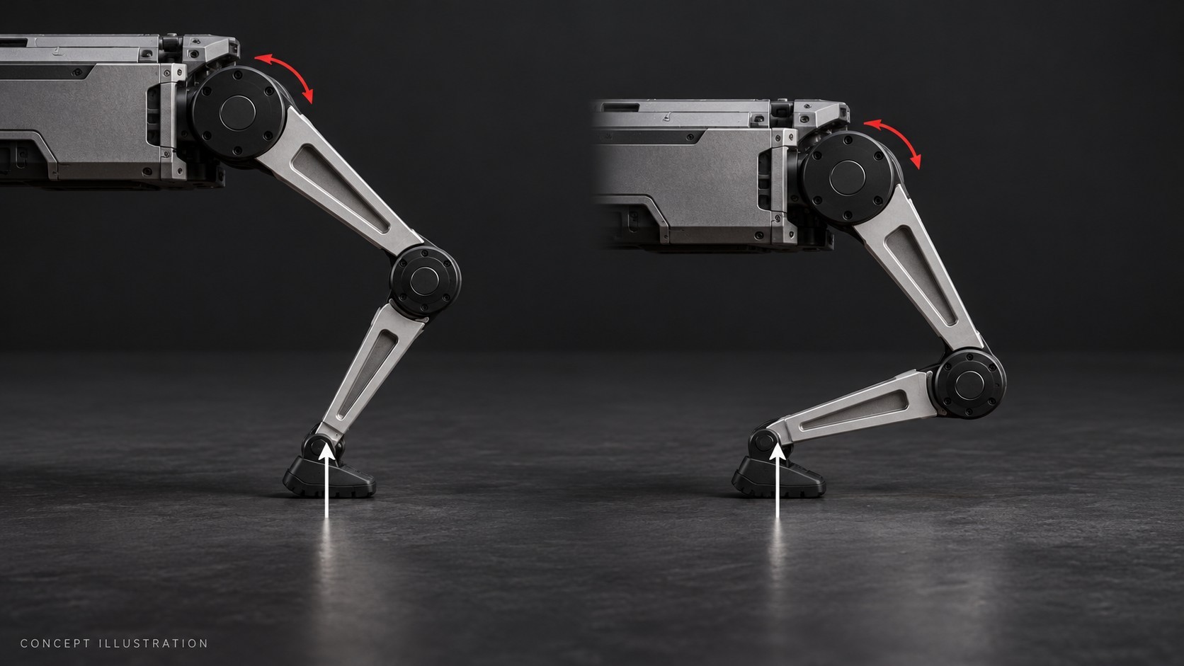
Record torque and speed together over time for each hip and knee axis. Base the model on leg geometry, body and payload mass, center of mass, link mass, foot clearance, joint travel and contact conditions. Include the intended walk, crouched hold and recovery step.
During stance, foot force changes with support contacts and load distribution. Dividing weight by four applies only to a particular static loading case. During swing, an unloaded foot still requires joint torque to accelerate the links and rotor.
The contact contribution is τcontact = J(q)TF. The Jacobian J maps joint motion to foot motion at posture q; it also maps contact force back to joint torque through its transpose. Use consistent coordinates and force signs. Add link-gravity, acceleration and friction torques without counting any load twice. See Northwestern University: the Jacobian force–torque relationship (external source).
| Phase | What the model must capture | What to check in the actuator |
|---|---|---|
| Stance and crouched hold | Foot-force distribution, joint moment arms, hold duration | Continuous or time-limited torque at low speed; installed cooling |
| Push-off and recovery | Simultaneous torque, speed and acceleration peaks | Peak duration, drive current, torque–speed envelope |
| Swing and foot placement | Link acceleration, reversal and required travel | Speed headroom, rotor and link inertia, tracking |
| Touchdown and disturbances | Contact velocity, compliance and load path | Mechanical shock limits, backdriving resistance, control response |
A small calculation shows why posture matters
Illustrative assumptions, not product specifications: take a 100 N vertical foot force. For one joint, a perpendicular moment arm of 0.12 m produces a 12 N·m contact contribution; at 0.06 m, it produces 6 N·m. These are two assumed geometric cases, not a statement that deeper crouching always increases torque. Link gravity, acceleration and other joint axes are omitted from this simple check.
For a preliminary forward-driving estimate, define reduction N = motor speed / joint speed and efficiency η. Then τmotor ≈ τjoint / (Nη) and ωmotor = Nωjoint. With assumed N = 8, η = 0.90 and joint speed 4 rad/s, the 12 N·m point maps to about 1.67 N·m at 32 rad/s on the motor shaft. Its joint mechanical power is 48 W; the estimated motor mechanical input to the gearbox is 53.3 W. This is not battery power, and it omits acceleration of rotating components and detailed losses.
2. Size for the repeated cycle, not one successful step
Plot the required torque–speed samples against the supplier’s operating envelope at the intended voltage, temperature and cooling, and check whether each lies within it. Include both directions and braking. Maximum torque and maximum speed may occur under different conditions: check the required pair, then its permitted duration and recovery time.
For a first copper-loss screen, use the actual motor-current history: Irms = √[Σ(Ii2Δti) / ΣΔti]. Keep the phase/line and peak/RMS conventions consistent with the winding resistance and torque constant. Resistive loss depends on current squared; OpenStax: electrical energy and resistive power (external source) explains the underlying principle.
Hypothetical one-second motor-current cycle: 2 A for 0.6 s, 5 A for 0.2 s and 1 A for 0.2 s gives Irms ≈ 2.76 A, despite an arithmetic mean of 2.4 A. These are assumed calculation inputs, not SolisMotor specifications, a measured gait or allowable current limits.
RMS is a copper-loss screen. Long holds and overloads need a time-dependent thermal check that also considers iron, gearbox and driver losses. Record initial temperature, ambient conditions and the installed cooling path. Read continuous torque versus peak torque before comparing catalog figures.
3. Choose reduction and feedback around contact behavior
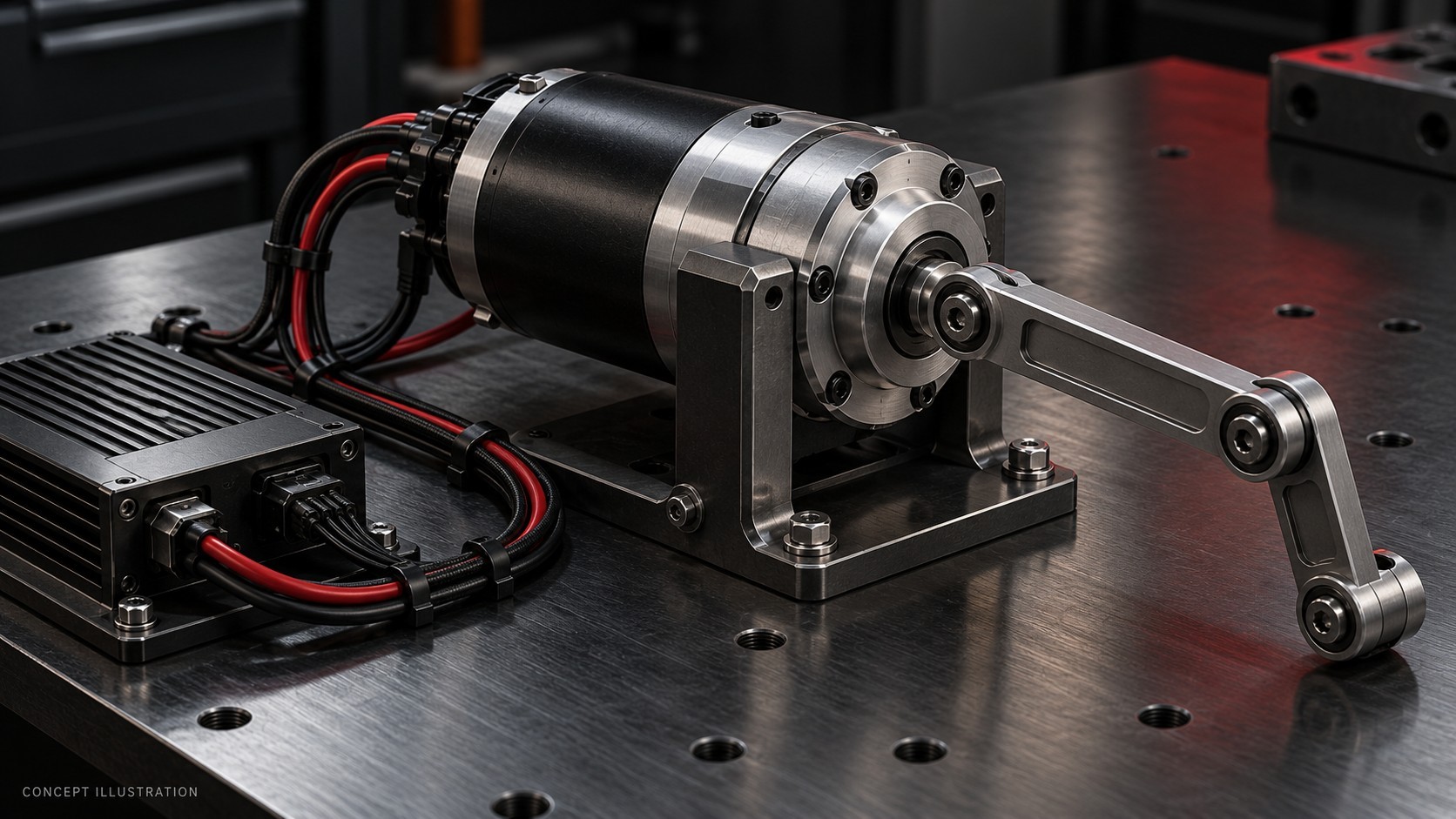
More reduction lowers the motor torque needed for a given forward-driven output load, while increasing motor speed for a given joint speed. It also changes the dynamics felt at the joint. For a simple rigid gear model, the rotor contribution reflected to the output is Jreflected = N2Jrotor; gearbox and link inertias must be added separately. Doubling N makes this rotor contribution four times larger if the rotor is unchanged. The convention and formula are documented by MIT Drake: reflected rotor inertia (external source).
Low ratios can help limit this inertia contribution, but may increase motor torque and current demand. Compare friction, compliance, backlash and contact response alongside the ratio. Use consistent test conditions when reading how QDD actuation works and what backdrivability means at the actuator output.
| Option | Potential reason to consider it | Evidence still needed |
|---|---|---|
| Low-ratio geared joint | Torque multiplication with comparatively limited rotor-inertia amplification for the same rotor | Actual output torque–speed curve, friction, thermal behavior and contact response |
| Higher-ratio geared joint | More forward-driving torque multiplication when motor size is constrained | Joint-speed headroom, reflected inertia, shock limits and backdriving behavior |
| Direct-drive joint | Eliminates gearbox friction, backlash and gear maintenance | Motor torque and mass, current demand, cooling and complete structural support |
Motor-side feedback measures rotor motion; output-side feedback measures position after the transmission. Dual encoders alone do not measure torque. Ask for encoder accuracy, latency, update rate, startup behavior and calibration data; bit count only describes resolution.
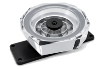
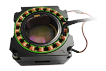
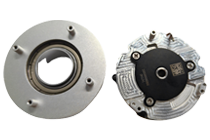
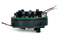
The SolisMotor MG8108-9 product page is an integrated planetary-joint reference for an initial shortlist. Use the confirmation table below to request the missing operating and integration evidence. The hypothetical calculations above do not qualify this model for a quadruped.
4. Qualify a representative leg before scaling to the robot
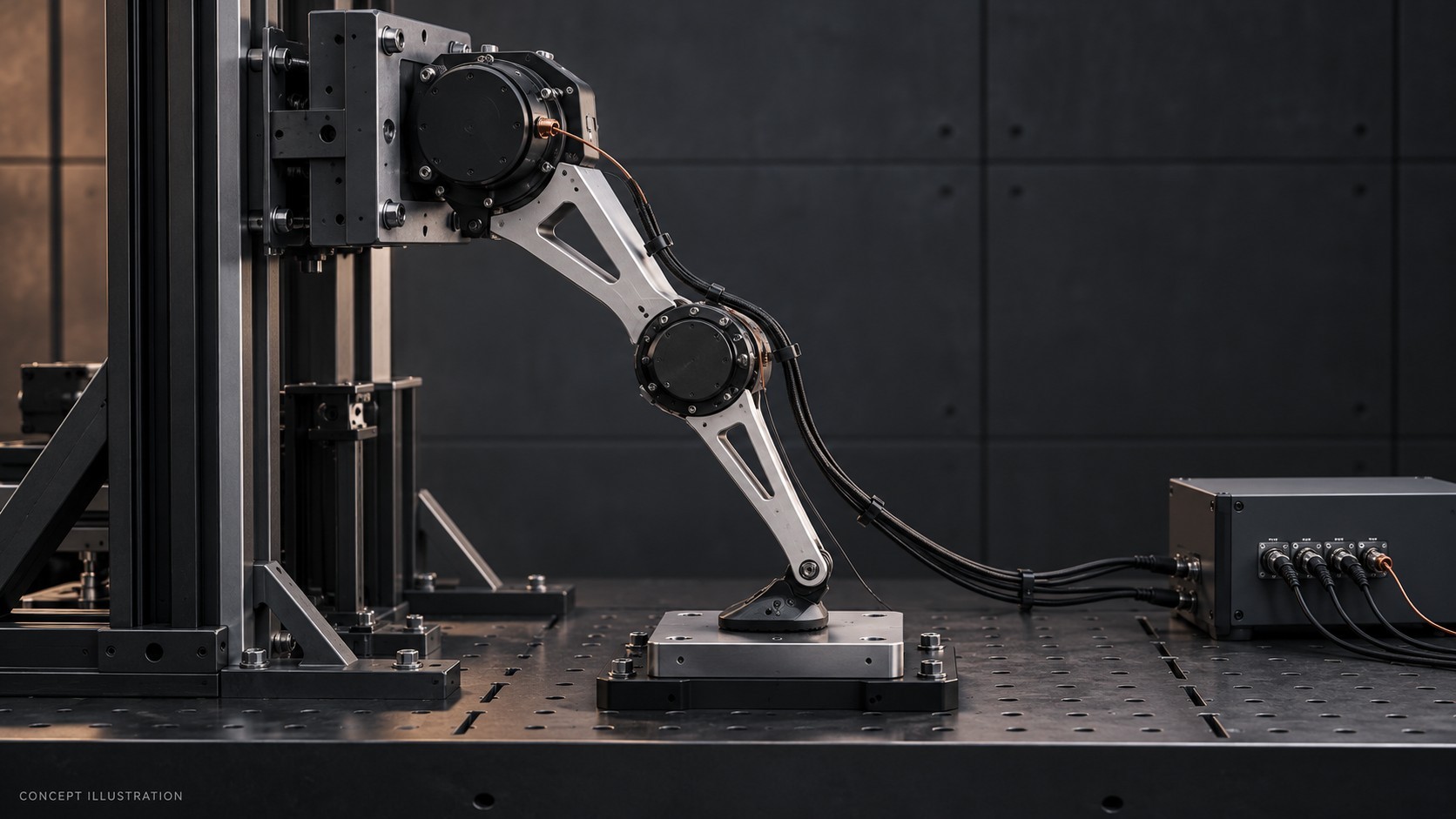
Set acceptance criteria for trajectory tracking, temperature, contact response and faults before testing. Progress from restrained joint/leg fixtures to supported whole-body trials under the project’s test procedure.
- Replay the working points. Use the intended links and payload representation. Record joint position, speed, measured or appropriately estimated torque, current and command timing together.
- Repeat the contact cycle. Include stance, swing, push-off, touchdown and a credible recovery maneuver. Inspect load paths, bearings, fasteners, cable travel and feedback continuity.
- Reach the relevant thermal condition. Test with the intended housing, mounting contact and cooling. Log motor and driver temperatures and any derating. A housing sensor is not automatically a winding-hotspot measurement.
- Check system interactions. Verify communication timing, voltage at the drive during simultaneous joint loading, braking-energy handling and the defined response to sensor, communication or power loss.
Keep phase current and DC-bus current distinct. Their relationship depends on switching and operating state. Also check the power system’s ability to accept or dissipate returned energy during deceleration; a motor-only test leaves that system question unresolved.
Complete one confirmation sheet per joint axis
| You provide | Ask the supplier to confirm | What remains provisional without it |
|---|---|---|
| Paired joint torque–speed history, gait and payload | Allowed torque–speed region at the stated voltage and temperature | Ability to follow the required working points |
| Peak duration, repetition, mission length and cooling/mounting | Overload/recovery limits, continuous rating conditions and thermal limits | Repeatable operation and thermal suitability |
| Reduction, travel, CAD envelope and external bearing loads | Drawing, shaft/bearing load ratings, backlash and friction data | Mechanical fit and load capacity |
| Feedback needs, communication timing and available power system | Sensor accuracy/latency, drive-current limits and braking-energy handling | Control and drive compatibility |
| Environment, cable routing, prototype quantity and test criteria | Applicable environmental evidence, interfaces and an agreed validation plan | Readiness for the intended installation and validation |
Keep the selection provisional if a required working point is unverified, overload recovery is unknown, or the rating’s cooling conditions differ from the installation. Record each gap and the calculation, supplier confirmation or test needed to close it. The SolisMotor robotic joint drive solutions overview describes application-selection and system-integration support.
Frequently asked questions
How much torque does a quadruped robot need?
There is no universal value. Calculate each joint from leg posture, contact forces, link dynamics and the intended gait. Robot weight alone does not capture moment arms, acceleration or changing support contacts.
Is peak torque enough to select a leg motor?
No. Check the simultaneous speed, allowable peak duration and repetition, repeated-load temperature and drive-current limits. Include crouched holds and recovery steps as well as normal walking.
Are QDD motors always the best choice?
No. Low-ratio geared joints can be useful for dynamic interaction, but the required torque, speed, mass, cooling, contact behavior and control performance must be evaluated together.
Can the same motor be used at every joint?
Possibly, if each axis meets its own operating and structural requirements. A common motor can simplify integration and spares, but may add unnecessary mass or leave one axis short of capability.
Does a high-resolution encoder guarantee accurate foot-force control?
No. Encoder accuracy and latency, torque estimation, transmission behavior, geometry calibration and controller response also affect the result. Validate foot-contact behavior on the assembled leg.
For an application review, share the completed input sheet and open questions through the SolisMotor contact page. Use the response to confirm a candidate and agree the leg-validation plan.