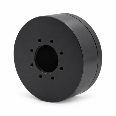
MG3505-8
 MG3505-9
 MG3505-36
 MG4315-8
 MG6010-6
 MG6010-8
 MG4305-10
 MG4310-10
 MG4310-36
 MG4310-40
 MG3510-8
 MG3510-64
 MG6010-36
 MG6010-48
 MG8108-6
 MG8108-8
 MG8108-36
 MG8108-48
 MG8115-6
 MG8115-9
 MG8115-36
 T-4024
 T-4929
 T-6034
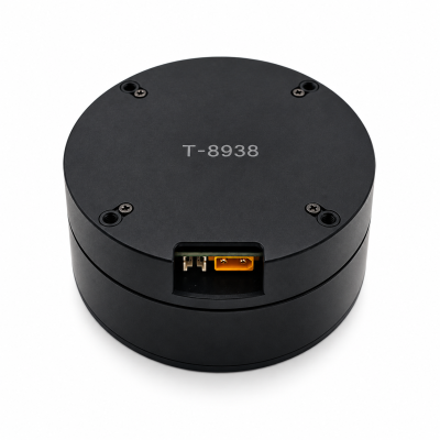
 T-8938
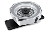
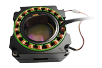
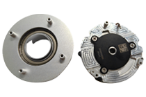
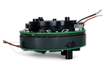
How to Build a BLDC Motor and Gearbox Actuator
To build a BLDC motor and gearbox actuator, turn the output task into a matched component set, resolve every mechanical and electrical interface, then verify the assembly before increasing duty. Work through the seven steps below. Each step produces a record that the next step needs: an output requirement, a component check, an assembly drawing, a connection plan or a measured result.
First compare the SolisMotor Robot Joint Motor range with the parts you plan to integrate. Check which functions are supplied and which your machine must add. This is an engineering integration guide for purchased components; use the selected hardware’s instructions for assembly details.
Cover illustration: original AI-generated integration concept, not a SolisMotor product photograph.
A seven-step BLDC gearbox actuator build workflow
1. Define the output task
Record output torque and speed together over time, travel, mounting direction, external forces and moments, ambient conditions and required position behavior. Include load cases such as holding, acceleration and stopping when relevant.
Deliver: an output-duty sheet with units, reference shaft and test conditions. Proceed when: the load cases are defined well enough to compare components; mark missing inputs rather than assume them.
2. Match the motor, reduction and drive
Translate the output duty to the motor shaft using a defined reduction and loss assumptions. Check the motor operating envelope, gearbox input-speed/output-torque limits and drive compatibility at the required points. Keep continuous duty and short peaks separate.
Deliver: a candidate list with the same duty boundary. Proceed when: the component limits and their conditions are documented; a ratio calculation alone cannot clear this gate.
3. Resolve the mechanical interfaces and output support
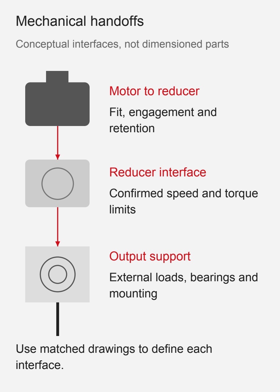
Check shaft engagement, retention, alignment, mounting faces, permitted input loads and the support of external output loads. Decide whether gearbox bearings provide the needed support or whether the machine adds it. Include cable travel, access and the path that carries heat into the machine.
Deliver: an assembly drawing, interface list and support arrangement. Proceed when: the load path and applicable fits, fasteners and assembly instructions are confirmed for the selected parts.
Worked example: start from a defined output target
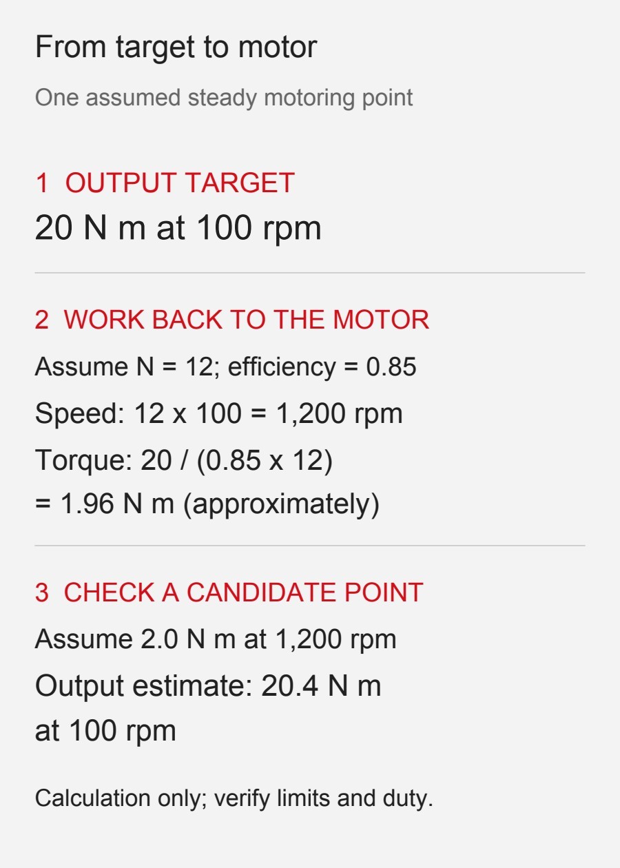
Assume a steady motoring target of 20 N·m at 100 rpm. Choose an assumed reduction N = 12 and a gearbox-only efficiency η = 0.85 at this point. With N defined as motor speed divided by output speed:
- Required motor speed: 12 × 100 = 1,200 rpm.
- Estimated motor torque: 20/(0.85 × 12) ≈ 1.96 N·m.
- A hypothetical motor point of 2.0 N·m at 1,200 rpm gives an estimated output of 0.85 × 12 × 2.0 = 20.4 N·m at 100 rpm. Its ideal, loss-free torque would be 24 N·m.
The arithmetic reaches the assumed target at one point. Before retaining the candidate, confirm that the motor can sustain that point under the stated cooling, the gearbox permits the input speed and output torque, and the output support accepts the external load cases.
Example boundary: all numbers are teaching assumptions, not SolisMotor ratings or test results. The efficiency applies to one steady motoring point using torque magnitudes; it is not a regeneration model or a constant for every duty. The 0.4 N·m difference is not an approved design margin. Northwestern University’s Choosing a Motor and Gearing Combination explains the underlying speed, torque and efficiency relationships.
Complete the configuration and verification steps
4. Prepare the drive and feedback connection plan
Document the motor/drive combination, supply range, phase-current and DC-bus-current definitions, feedback interface, signal direction, required commutation information and how sensor counts convert to output angle. Follow the selected hardware’s pinout and configuration instructions.
Deliver: a connection diagram and parameter sheet. Proceed when: motor, drive and sensor information agree. The robot joint encoder guide helps define the measurement boundary.
5. Review the assembly with power isolated
Reconcile the built assembly with the released drawings and component instructions. Review retention, clearances, cable routing, connectors, output support and the planned test setup. Resolve discrepancies before energizing.
Deliver: an assembly review record. Proceed when: the required assembly checks are complete, discrepancies that prevent the planned test are resolved, and the responsible team has accepted the setup and safeguards under its bench procedure.
6. Check restricted bench motion
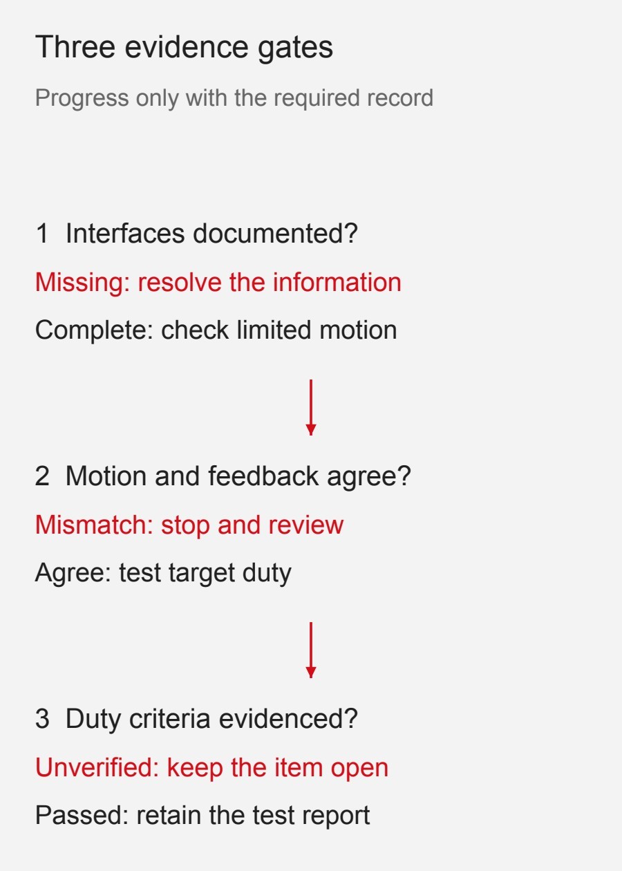
Use the agreed restrained setup and hardware-specific limits to check direction, feedback sign, travel and output scaling. Compare observed output motion with the configured feedback. If behavior disagrees, stop the test and return to the connection or mechanical review.
Deliver: a limited-motion log identifying the configuration and observations. Proceed when: behavior matches the documented configuration and the procedure’s criteria.
7. Verify the target duty
Add representative load only after the earlier gates pass. Record synchronized motion, electrical conditions, temperatures and output behavior through the agreed cycle. State each acceptance limit and mark the result passed, failed or unverified.
Deliver: a duty-test report linked to the assembly revision. Approve the combination when: the required criteria have evidence; leave untested combinations open. The robot joint heat-management guide explains why the installed heat path matters during loaded testing.
When the assembly behaves differently than expected
Use observations to decide what to investigate. The table lists possible checks, not confirmed causes; follow the hardware-specific diagnostic procedure before changing wiring or settings.
Table: swipe horizontally to see all three columns.
| Observation | Possible check directions | Information to confirm |
|---|---|---|
| Observed direction and feedback sign disagree | Command convention, sensor direction, transmission direction and output scaling | Connection diagram, drive configuration and independent motion observation |
| Unloaded motion works; loaded temperature exceeds an agreed limit | Actual duty/current, alignment or friction, cooling path and transmission losses | Synchronized load/current/temperature records and confirmed operating limits |
| Output position differs from the expected value | Reference setting, sensor location/scaling, transmission lost motion, support compliance or load effects | Output measurement conditions, mechanical drawing and feedback configuration |
The strain-wave versus planetary gearbox guide provides context for transmission trade-offs. MIT’s Robotic Manipulation notes also explain why motor-side behavior alone does not establish complete joint behavior.
Frequently asked questions
Is a motor and gearbox a complete actuator?
Check the supplied functions. Output support, drive electronics, sensing, cables and thermal interfaces may still need to be provided by the machine builder.
Does the 20.4 N·m example qualify a motor?
No. It is one assumed arithmetic point. The seven-step workflow adds component-limit checks and installed verification before a combination can be approved.
Can the motor encoder replace an output measurement?
Define the measurement boundary. Verify the assembled output when judging output positioning, including the effects of the transmission, support and load.
What should an OEM send for an integration review?
Send the output-duty sheet, candidate component list, proposed assembly drawing, connection/configuration plan and unresolved questions. Use the SolisMotor engineering-services overview for scope discussions and submit the package through the SolisMotor contact page.