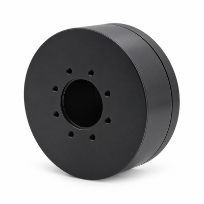
MG3505-8
 MG3505-9
 MG3505-36
 MG4315-8
 MG6010-6
 MG6010-8
 MG4305-10
 MG4310-10
 MG4310-36
 MG4310-40
 MG3510-8
 MG3510-64
 MG6010-36
 MG6010-48
 MG8108-6
 MG8108-8
 MG8108-36
 MG8108-48
 MG8115-6
 MG8115-9
 MG8115-36
 T-4024
 T-4929
 T-6034
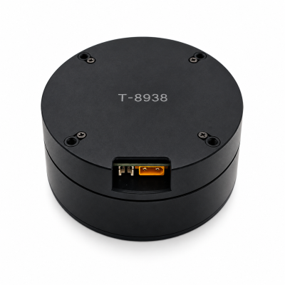
 T-8938
How Robot Joint Actuators Enable Humanoid Walking
Robot joint actuators enable humanoid walking by producing coordinated torque and motion as support shifts between the feet. The drive must support the loaded leg, reposition the swinging leg and respond to contact changes within its verified limits. Stable walking also requires body-state estimation, contact sensing or estimation, and whole-body control; a powerful motor alone does not provide balance.
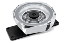
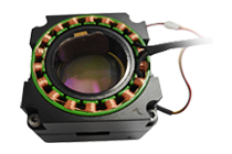
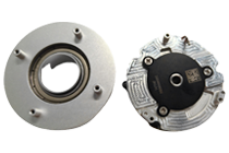
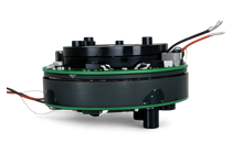
For an initial hardware overview, explore the SolisMotor Robot Joint Motor range. This article follows the walking task itself: what changes at foot contact, how the leg joints share the work, and what evidence an OEM should request before calling an actuator suitable for a walking platform.
Walking changes the actuator task at every contact transition
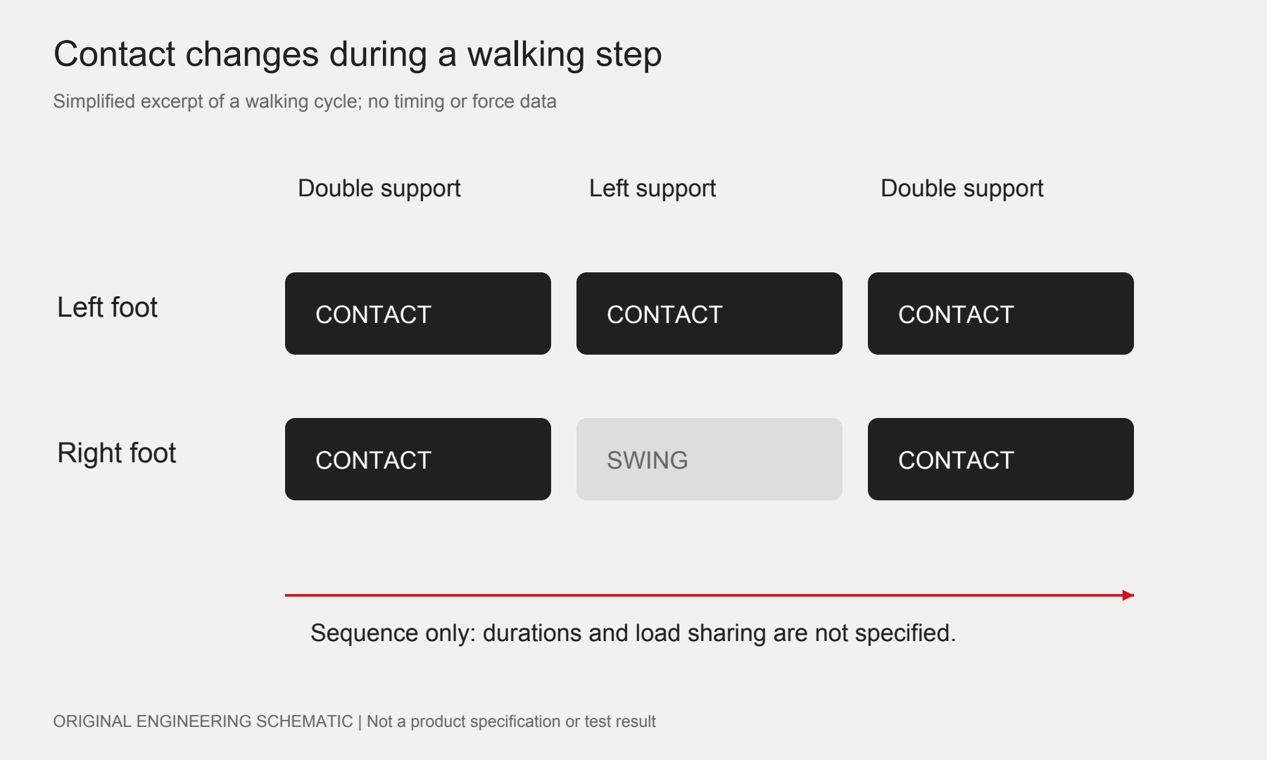
In ordinary walking, support alternates between one foot and two feet. The stance leg interacts with the ground while the other leg can move toward the next foothold. Ground forces, joint motion and body momentum must remain compatible with the active contacts. MIT’s Underactuated Robotics notes on legged-robot contact dynamics (external source) explain why walking cannot be reduced to tracking a sequence of joint angles.
For a development specification, separate three events instead of giving the supplier only an average walking speed:
- Load transfer: how support moves from the trailing foot to the leading foot, including the desired contact sequence.
- Single support and swing: the loaded leg’s required motion while the other foot clears the floor and approaches its next placement.
- Touchdown: the allowed approach velocity, contact response and transition into the next support phase.
Diagram: swipe horizontally on small screens.
Hip, knee and ankle actuators do different work
The joint names identify locations, not interchangeable load ratings. For a leg with powered hip, knee and ankle axes, use the following functional questions to organize the design review. Exact roles depend on the mechanism, degrees of freedom and gait.
| Joint region | Walking function to examine | Evidence to request |
|---|---|---|
| Hip | Leg placement and coordination of pelvis/leg motion | Required motion on each axis, cable travel and loads through the joint support |
| Knee | Leg length and foot-clearance changes; support under the chosen posture | Torque–speed history through stance, swing and any crouched hold |
| Ankle | Foot orientation and ground-interaction behavior in the chosen foot design | Travel limits, bearing/load path and contact response at the output |
Do not assign the same actuator merely because the housings fit. Conversely, shared hardware can be reasonable when each axis independently meets its requirements. Confirm the delivered scope: motor, transmission, bearings, encoder and drive may be supplied in different combinations. The SolisMotor humanoid joint-drive solutions overview provides a relevant starting point for that integration discussion; it is not proof that a particular assembly has passed a walking test.
Why body weight alone does not determine joint torque
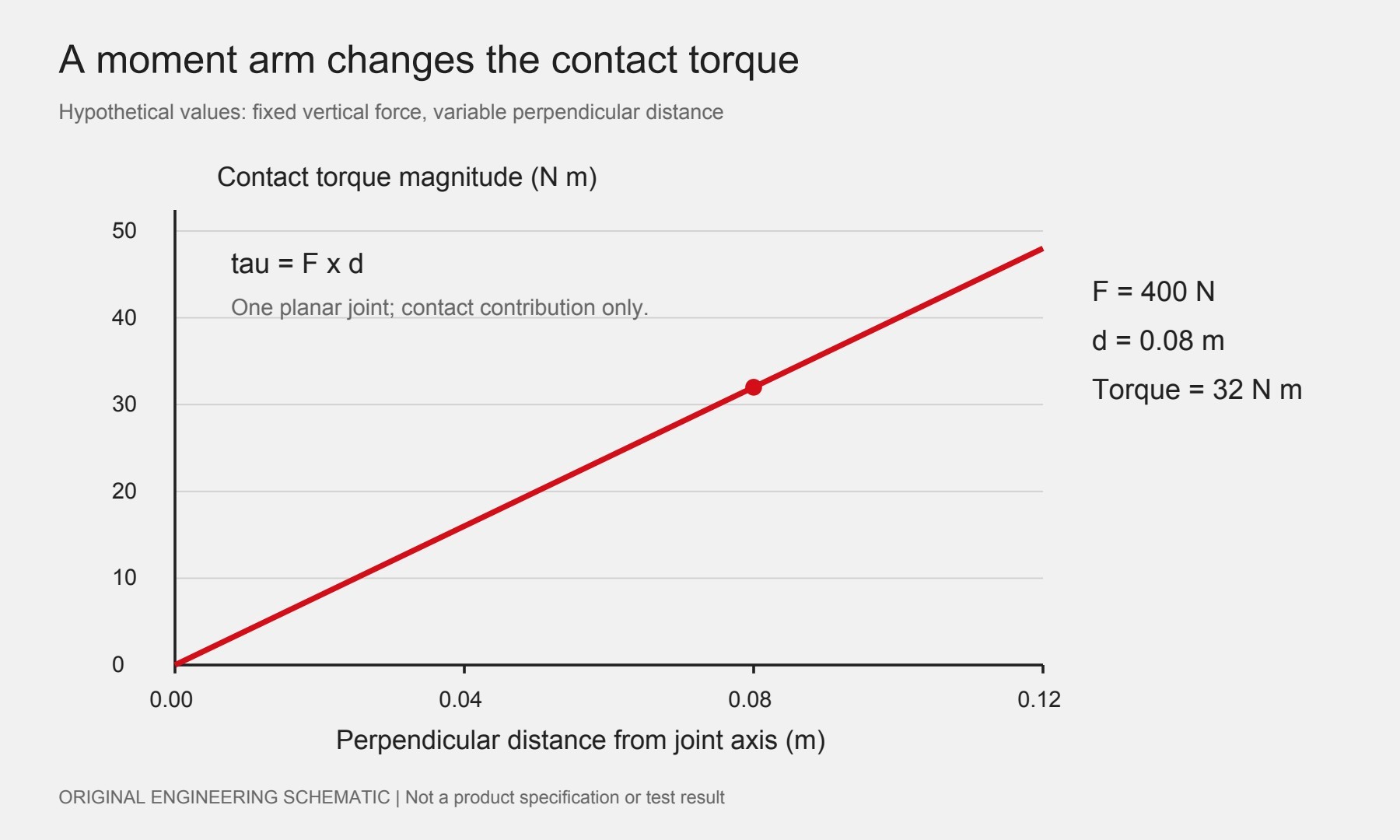
A force produces a moment according to its perpendicular distance from a joint axis. For a general articulated chain, the Jacobian transpose maps a specified end-effector wrench to a joint load contribution; use consistent frames and signs. See Northwestern University: statics and the Jacobian transpose (external source). Full walking inverse dynamics must also account for link motion, gravity and the floating body; a static force calculation is only one contribution.
Hypothetical planar contact-load example
Assume a vertical foot force of 400 N and a perpendicular distance of 0.08 m from its line of action to one joint axis. The contact moment magnitude is:
400 N × 0.08 m = 32 N·m
If that distance becomes 0.04 m while the assumed force stays 400 N, the contribution becomes 16 N·m. This comparison changes one geometric input; it does not establish a universally better leg posture. The values are invented teaching assumptions, not measured forces, actuator ratings or a SolisMotor case.
The resulting moment is not yet a motor-selection value. Add the other modeled contributions with correct signs, evaluate the complete motion, and pair torque with speed and duration. The continuous-versus-peak torque guide explains why a brief overload value cannot stand in for repeatable stance capability.
Diagram: swipe horizontally on small screens.
Walking needs feedback beyond a position command
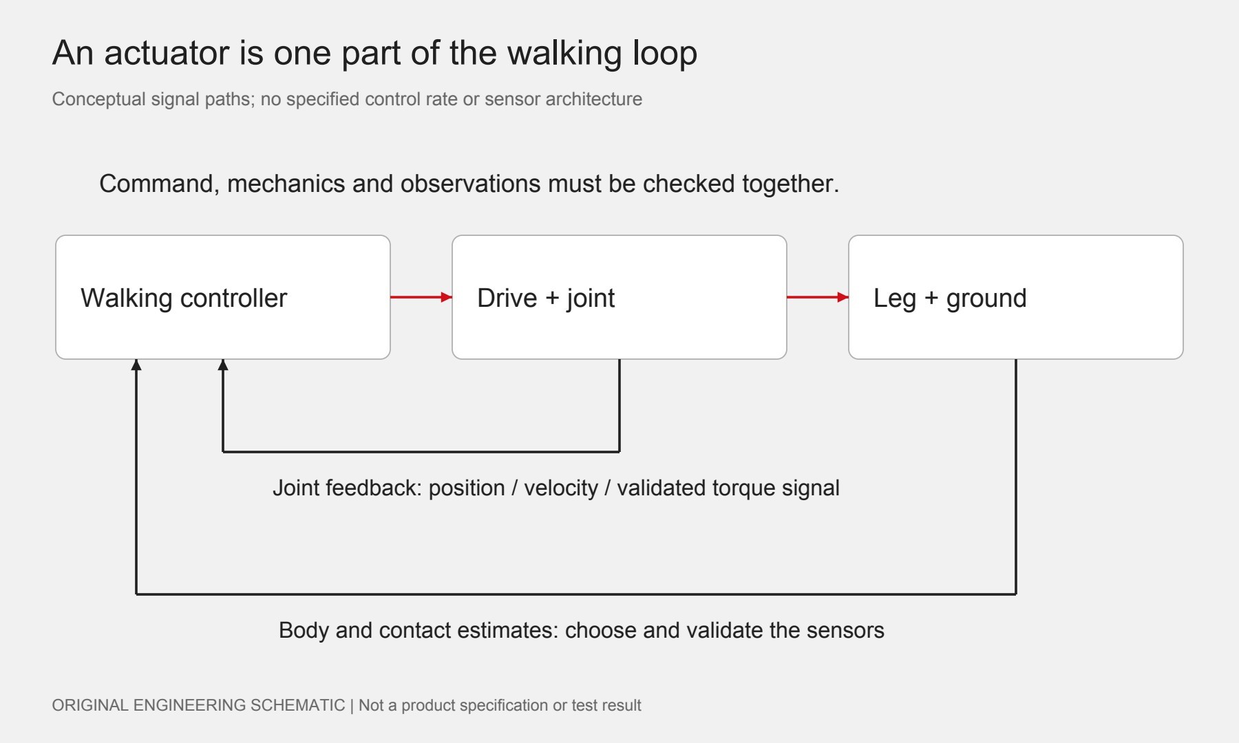
A joint can follow a command on a bench yet behave differently after installation. For the walking review, ask what the controller actually observes at the output and how old that information is. Document position calibration, velocity estimation, timestamps, communication delays and the handling of missing samples.
An encoder reading is not automatically a foot-force measurement. If torque is estimated from current, validate the estimate against the actual transmission, friction and operating conditions. If a force/torque sensor is used, define its installation, calibration and usable measurement range. The SolisMotor encoder selection guide helps frame the position-feedback discussion.
Mechanical interaction matters too. Examine friction, lost motion and compliance alongside the control strategy. The backdrivability guide explains one interaction property; it is not a guarantee of stable touchdown. An OEM should specify the contact response it wants to demonstrate, rather than accept “smooth walking” as an unmeasurable requirement.
Diagram: swipe horizontally on small screens.
Turn “can it walk?” into an evidence request
Keep component capability and whole-robot performance as separate acceptance decisions. Before a walking trial, agree a staged, restrained test procedure appropriate to the robot and its hazards. Then organize the evidence around specific questions:
- Can the joint reproduce its assigned phase? Replay the specified torque–speed–time history with representative mounting and load. Record any clipping, current limiting or thermal derating.
- Does the leg make the intended contact? Compare planned and observed foot placement, clearance, contact timing and response under the agreed supported test conditions.
- Does performance repeat? State the cycle count or mission duration, ambient conditions, payload, footwear/surface and cooling. Record tracking and temperature over the complete trial.
- What happens when a signal or supply disappears? Demonstrate the defined response to communication, feedback or power loss using the project’s safeguards. Do not assume an unpowered motor holds the robot upright.
Provide these questions with a per-axis operating history and the leg drawings through the SolisMotor application inquiry page. Request confirmed interfaces, operating limits and the specific test evidence still needed. No product in the catalog is qualified for a particular humanoid gait by the hypothetical calculation in this article.
Frequently asked questions
Do all humanoid robots need powered ankles?
No universal joint layout follows from the word “humanoid.” Define the foot design, required motions and balance strategy, then review whether each intended degree of freedom is powered, passive or mechanically coupled.
Does higher peak torque guarantee better walking?
No. It answers only one hardware question. The project must also demonstrate the required motion, contact response, repeated-load capability and coordination within confirmed operating limits.
Can a joint actuator balance the robot by itself?
A local drive can regulate its own controlled quantities. Whole-body balance requires the relevant body and contact information and coordination of the robot’s available actions; it is not a motor nameplate feature.
What should a buyer send before asking for a recommendation?
Send the joint layout, mass and payload assumptions, intended contact sequence, per-axis operating histories, installation drawings and measurable acceptance criteria. Mark assumptions and missing data explicitly.