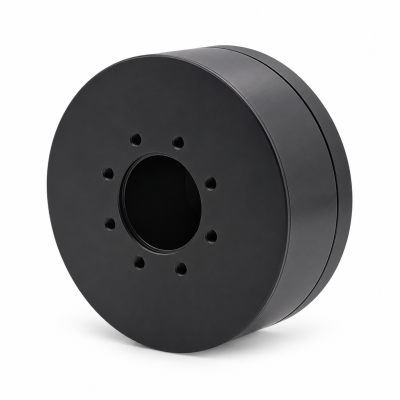
MG3505-8
 MG3505-9
 MG3505-36
 MG4315-8
 MG6010-6
 MG6010-8
 MG4305-10
 MG4310-10
 MG4310-36
 MG4310-40
 MG3510-8
 MG3510-64
 MG6010-36
 MG6010-48
 MG8108-6
 MG8108-8
 MG8108-36
 MG8108-48
 MG8115-6
 MG8115-9
 MG8115-36
 T-4024
 T-4929
 T-6034
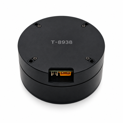
 T-8938
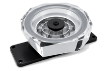
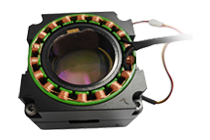
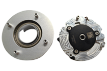
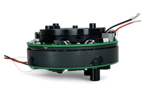
How Does a Strain-Wave Geared Robot Joint Actuator Work?
How does a strain-wave geared robot joint actuator work? An elliptical wave generator flexes a toothed flexspline against a rigid circular spline. The moving engagement zones and tooth-count difference turn fast input into slow output. Ratio and direction depend on which member is fixed. Bearings, motor, feedback, cooling and controls complete the joint; the reducer alone does not define loaded accuracy.
Strain-wave gearing is often described as a “harmonic” drive in robotics. This article explains the mechanism and the tests that matter when integrating it into a joint. For the available assembled options, start with SolisMotor's robot joint motor and actuator range; request a configuration-specific drawing before assuming any one model uses the mechanism described here. The Robot Joint Motor Technical Guides collects the related integration articles.
The three parts that create the reduction
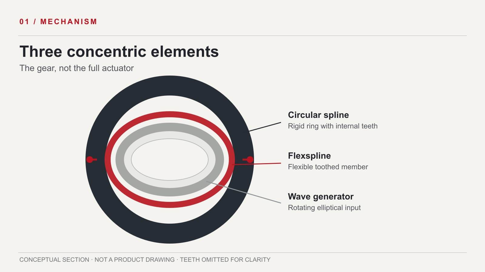
A basic strain-wave gear has three concentric elements. The wave generator is an elliptical input, usually carried by a flexible bearing. The flexspline is the deformable externally toothed member. The circular spline is a rigid internally toothed ring. The wave generator pushes the flexspline outward along its major axis, so teeth mesh mainly in two opposite regions. Motor, encoder, output bearing, brake, and housing belong to the larger actuator architecture, not automatically to the reducer itself.
| Element | Mechanical role | What a buyer should verify |
|---|---|---|
| Wave generator | Rotates an elliptical deformation wave into the flexspline. | Input interface, bearing arrangement, allowable speed, lubrication conditions. |
| Flexspline | Flexes elastically and carries external teeth that engage the ring. | Output or fixed-member arrangement, load limit, fatigue and service conditions. |
| Circular spline | Provides the rigid internal-tooth reference. | Whether it is fixed or the output, mounting fit, and alignment requirement. |
How rotation becomes slower output motion
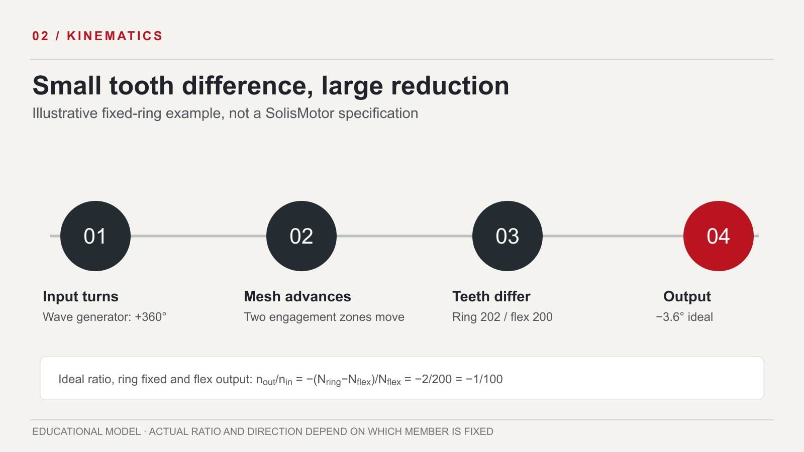
- The motor turns the wave generator. Its elliptical shape rotates inside the flexspline; the flexspline material does not spin one-for-one with this deformation wave.
- Two meshing regions travel around the ring. The flexspline teeth engage the circular spline near the two ends of the ellipse's major axis. The meshing locations advance with the wave generator.
- A tooth-count difference creates relative rotation. The flexspline has slightly fewer teeth than the circular spline in a typical configuration. Each circuit of the engagement pattern shifts the flexspline relative to the ring by the tooth difference.
- The chosen fixed and output members set the result. In a common reducer arrangement, the circular spline is fixed, the wave generator is the input, and the flexspline is the output. Other layouts can reverse the output member or change the ratio and direction.
For a purely idealized example, suppose a fixed circular spline has 202 teeth and the output flexspline has 200. One positive turn of the wave generator yields approximately −2/200 turns, or −3.6°, at the flexspline: an ideal reduction of 100:1 in the opposite direction. This is a kinematic teaching example, not a SolisMotor gear ratio, drawing, or test result. Real output motion also includes elastic deflection, friction, manufacturing error, and load-dependent behavior. For load-side calculations that use a selected ratio, see the robot joint torque and speed calculation guide.
Why low backlash is not the same as perfect joint accuracy
Multiple teeth share engagement, and the gear can be designed for very small clearance at the mesh. But low tooth backlash does not eliminate output error. Flexspline torsion and bending, bearing compliance, friction, mounting error, and control behavior can produce load-dependent lost motion or hysteresis. A peer-reviewed JSME study of strain-wave gear torsional rigidity — external source treats flexspline deformation as a contributor to the stiffness observed at the output. For a robot, specify the loaded output behavior rather than inferring accuracy from a reducer's nominal ratio alone.
Backdrivability is also a system property: reduction, friction, motor torque, brake state, and controller all matter. The robot actuator backdrivability guide explains what to measure if human interaction or compliant motion is part of the requirement. A reducer label alone cannot establish a safe contact behavior.
What the assembled robot joint must add
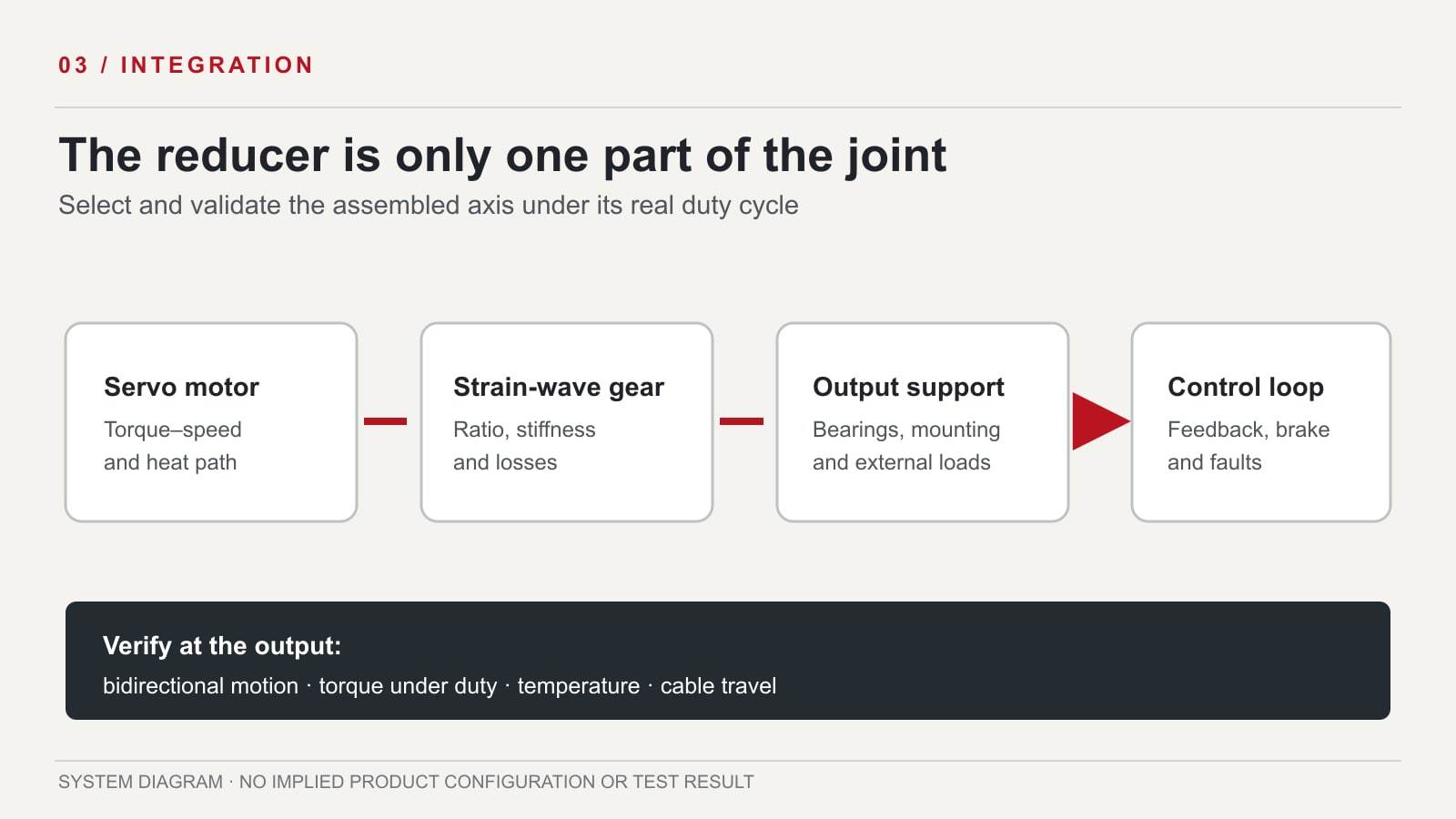
Outside the three-member gear, a usable actuator still needs a motor matched to the duty cycle, support for external and axial loads, position feedback at the appropriate side of the transmission, heat paths, wiring, and fault handling. Some designs add a brake. To define what feedback can measure, use the incremental versus absolute encoder selection guide, then confirm whether the selected encoder measures the motor or the actual joint output. SolisMotor's humanoid robot joint drive solution overview provides the broader system context; the exact delivered bill of materials and qualification data must be confirmed for the selected configuration.
| Question | Evidence to request | Why it matters |
|---|---|---|
| What output torque and speed are required through the duty cycle? | Torque–speed trace, peak duration, ambient and mounting conditions. | Continuous thermal capability cannot be inferred from peak torque alone. |
| How much loaded output error is acceptable? | Bidirectional positioning and stiffness measurements under stated load. | Nominal ratio and small mesh clearance do not specify complete-axis accuracy. |
| Where are external loads carried? | Mounting drawing, bearing limits, axial/radial load paths. | The flexspline and reducer may not be the intended output support. |
| What happens after power loss or a fault? | Encoder arrangement, brake state, controller fault behavior. | Position retention and contact behavior depend on the assembled axis. |
| What service conditions apply? | Lubrication, temperature, cycle life and maintenance basis for the specific unit. | Friction, wear and stiffness can change with use and environment. |
Use this checklist when reviewing the robot joint actuator configurations against the humanoid joint drive integration requirements. Verify the transmission type and delivered scope with the configuration-specific drawing.
Frequently asked questions
Is a strain-wave gear itself a complete robot joint actuator?
No. It is a reduction mechanism. The actuator also needs a motor, appropriate support bearings and housing, feedback, controls, and often a brake or thermal design. Confirm the actual delivered scope for the selected model.
Does a 100:1 gear make output torque exactly 100 times motor torque?
No. The ideal speed ratio is a kinematic relationship; delivered torque depends on mechanical efficiency, speed, direction, temperature, and duty. Inertia and external loads add further system-level requirements. Request a measured or validated torque–speed basis for the intended assembly.
Is the 202/200-tooth example a SolisMotor specification?
No. Those counts are invented solely to illustrate how a two-tooth difference can create an ideal 100:1 reduction when the ring is fixed and the flexspline is the output. Do not use them to select a product.
Does low backlash mean the joint has zero lost motion?
No. Elastic deformation, bearing compliance, friction, manufacturing variation, and mounting can create load-dependent output movement even when tooth clearance is small. Compare measured bidirectional output behavior under the application's load.
Can the output be driven backward by an external force?
Possibly, but the answer depends on reducer friction and ratio, motor and controller state, brake, and load. Test the complete powered and unpowered axis for the intended interaction scenario.
To evaluate an actual configuration, send the required joint motion, continuous and peak torque durations, available envelope, external loads, feedback requirements, and thermal conditions through the SolisMotor engineering contact page for robot joint selection. Request its specific drawing and test basis before freezing the design.