BLDC Motor vs Servo Motor: What Is the Difference?
Oct 9,2026
Motor terminology · Robot joint selection
BLDC describes a motor family. Servo describes how a motion system uses feedback to follow a command. A brushless DC motor can therefore be part of a servo system. For a robot joint, compare the motor, drive, feedback and mechanical output together, rather than treating “BLDC” and “servo” as competing technologies.
A brushless DC motor uses electronic switching to energize its windings instead of a mechanical brush-and-commutator arrangement. Permanent magnets and the energized windings interact to produce rotation. The power electronics and commutation method must match the motor.
Suppliers use BLDC and PMSM terminology with different levels of specificity. Check the winding, back-EMF and drive requirements rather than assuming a label fixes the control method. Microchip’s motor-family overview explains this relationship.
Servo: the controlled motion
A servo system compares a command with feedback and adjusts its output to reduce the error. In a positioning axis, this often involves position, speed and current regulation. The word “servo” alone does not specify the motor construction, gearbox, feedback resolution or achievable joint accuracy.
BLDC motor vs servo system: a useful comparison
The two columns describe different layers of the same possible assembly. Neither label, by itself, establishes a performance advantage.
On narrow screens, swipe across the table to see all columns.
Questions to resolve before comparing quotations
Question
BLDC motor
Servo system
What does the term identify?
A brushless, electronically commutated motor family.
A feedback-controlled motion function.
What about feedback?
The motor label does not tell you which sensors or control loops are included.
Feedback must support the controlled variable and required operating range.
What hardware is supplied?
It may be a bare motor or an integrated assembly. Read the scope of supply.
Confirm the motor, drive, feedback device and interfaces; packaging varies.
Does it guarantee precision?
No. The drive, sensing and mechanics still matter.
No specific accuracy follows from the label. Ask for measured results and conditions.
Can both terms apply?
Yes. A BLDC motor can operate within a compatible servo system.
Commutation and motion feedback solve different problems
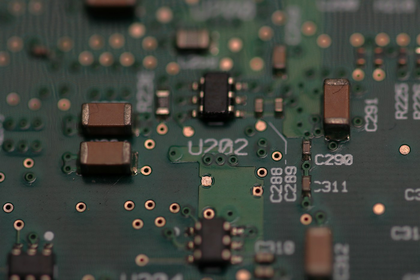
Illustrative electronics photograph; not a SolisMotor controller or a verified motor-drive circuit. Photo by Gabriel Vasiliu on Unsplash · License.
Commutation determines how the windings are energized as the rotor moves. A position-control loop asks a different question: is the axis where the command says it should be? A controller may handle both tasks, but they should be specified separately.
Hall signals used for commutation do not, on their own, establish a precision-positioning specification. Likewise, adding an encoder does not automatically create a tuned, validated servo axis. Feedback type, signal processing and control behavior must work together. See the BLDC commutation reference.
Do not confuse FOC with a complete servo axis
Field-oriented control (FOC) is a motor-control method. It can be used within a servo system, but “FOC” on a specification does not tell you that load-position control is included. “Sensorless” also does not mean there are no measurements or feedback: some methods estimate rotor state from electrical signals. Microchip documents describe encoder-based FOC and sensorless estimation.
Specify the motion before choosing the hardware
For an OEM robot joint, a useful enquiry describes what the assembled axis must do. The following checklist is an engineering starting point, not a product performance guarantee.
Motion task. Define continuous rotation, repeated positioning or controlled joint torque. State travel, speed, acceleration and the time spent holding a position.
Load and duty cycle. Include load inertia, external forces, friction and the operating sequence. Separate continuous requirements from short peak events.
Electrical and thermal limits. Provide the available supply, current limits, enclosure and cooling conditions. Compare the usable torque–speed range under those conditions.
Feedback and control. Specify required control modes, feedback location and startup behavior. Treat encoder resolution, repeatability and absolute joint accuracy as separate requirements.
Mechanical and communication interfaces. Check gearbox ratio, backlash, shaft or bore geometry, mounting, wiring and the actual supported communication protocol.
Acceptance tests. Agree on load conditions, following error, settling behavior and temperature rise. Define what the mechanism should do during a power loss or fault.
How this distinction applies to SolisMotor products
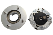
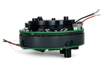
Two current SolisMotor listings illustrate why the complete configuration matters. They are examples of integration choices, not interchangeable recommendations.
On narrow screens, swipe across the table to see all columns.
Selected listing details checked on October 8, 2026
An integrated brushless motor, servo driver and 20-bit single-turn absolute encoder, with a 31 mm hollow bore.
Cable routing, required control mode and whether the complete assembly meets the positioning requirement.
These encoder specifications do not imply a direct accuracy ranking between the products. SolisMotor’s engineering services include motor, gearbox and drive matching, along with prototype validation. A motion brief gives that discussion a concrete starting point.
One joint can be both brushless and servo-controlled
Consider an illustrative robot joint that moves to a target angle and holds while the external load changes. “Brushless” describes the motor construction. “Servo-controlled” describes how the assembled axis uses feedback to follow the target. The gearbox and feedback location then influence what the controller can observe at the output.
This is a hypothetical design discussion, not a SolisMotor customer case. A practical evaluation would test the assembled joint with representative loading and the intended motion profile.
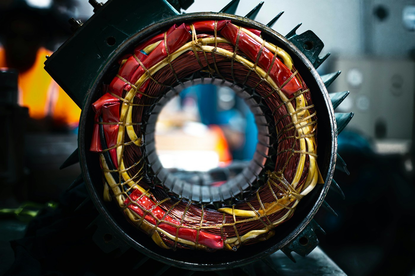
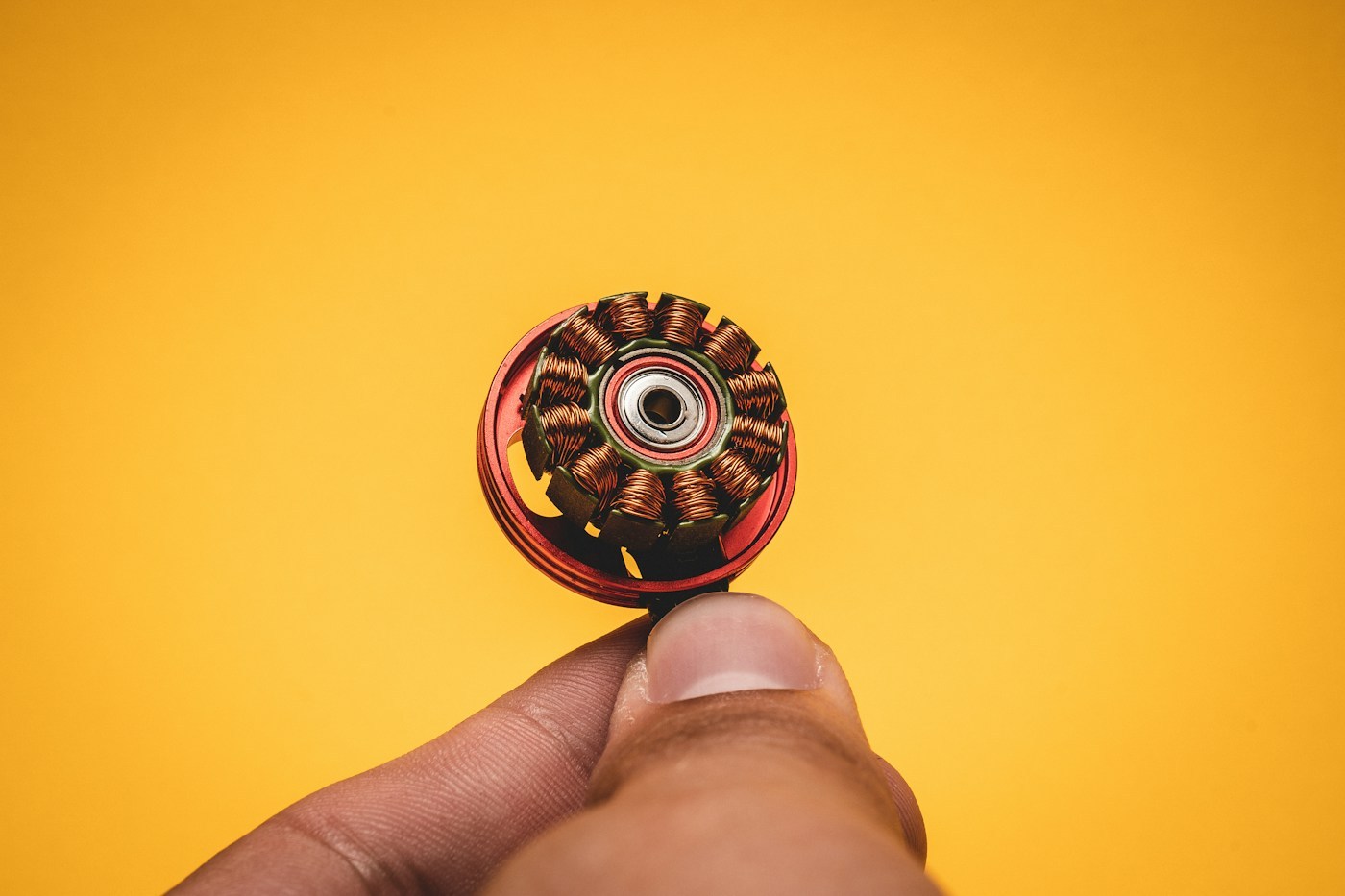
Illustrative small-motor photograph; not a SolisMotor product. Photo by Mika Baumeister on Unsplash · License.
Frequently asked questions
Can a BLDC motor be used as a servo motor?
Yes, as part of a compatible system with appropriate feedback and control. The motor alone does not guarantee servo performance; the drive, mechanics and tuning must also meet the application requirements.
Is a BLDC motor always open-loop?
No. BLDC drives can use measured or estimated information in closed-loop control. Ask which variable is controlled and how its feedback is obtained.
Is a servo motor always brushless?
No. Servo operation is possible with other motor constructions. For example, Microchip’s AN532 demonstrates a brushed DC motor with encoder-based servo control. The example establishes the principle, not a recommendation to use its older hardware.
Which is more accurate or less expensive?
The labels cannot answer that. Compare complete systems against the same motion task, load, thermal conditions and acceptance criteria, including feedback, drive and integration costs.
Technical references
The comparison and checklist are independently written from the linked technical material and current SolisMotor product listings. External manufacturer references support technical definitions; they do not indicate a partnership or endorsement.

 MG3505-8
 MG3505-9
 MG3505-36
 MG4315-8
 MG6010-6
 MG6010-8
 MG4305-10
 MG4310-10
 MG4310-36
 MG4310-40
 MG3510-8
 MG3510-64
 MG6010-36
 MG6010-48
 MG8108-6
 MG8108-8
 MG8108-36
 MG8108-48
 MG8115-6
 MG8115-9
 MG8115-36
 T-4024
 T-4929
 T-6034
 T-8938