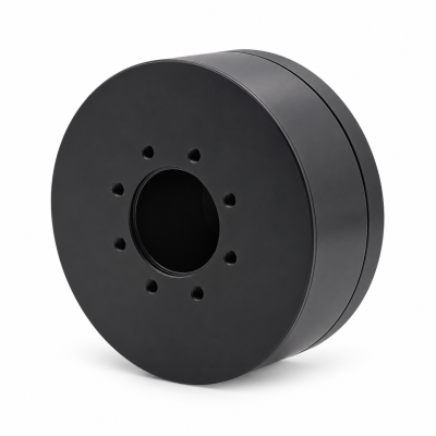
MG3505-8
 MG3505-9
 MG3505-36
 MG4315-8
 MG6010-6
 MG6010-8
 MG4305-10
 MG4310-10
 MG4310-36
 MG4310-40
 MG3510-8
 MG3510-64
 MG6010-36
 MG6010-48
 MG8108-6
 MG8108-8
 MG8108-36
 MG8108-48
 MG8115-6
 MG8115-9
 MG8115-36
 T-4024
 T-4929
 T-6034
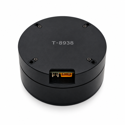
 T-8938
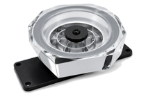
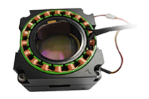
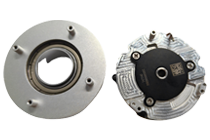
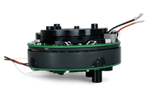
The Rise of Electric Actuators in Humanoid Robots
Electric actuators appeal to humanoid robot designers because motors, drives and feedback can form a controllable joint architecture with clearly defined electrical and mechanical interfaces. The important decision is the complete installed system: transmission, sensing, power supply and heat path all affect the result. Electric actuation is not automatically the best answer for every joint.
Start with the SolisMotor Robot Joint Motor range to define the supplied functions, then compare the remaining integration work. This article explains engineering reasons behind interest in electric actuation; it does not estimate market share or claim that hydraulic systems have disappeared.
Cover: original AI-generated concept, not a SolisMotor product photograph, robot or customer installation. Technical context checked 4 November 2026.
What the trend does—and does not—tell a buyer
Russ Tedrake’s MIT Robotic Manipulation notes describe a trend toward electric motors while also discussing hydraulic and other torque-control architectures. This is useful technical context, not a current census of humanoid production. It supports examining electric solutions, not declaring one technology universally superior.
For an OEM, a trend is a starting point for questions. Ask which architecture meets the actual task and what evidence demonstrates it. Use a data sheet to shortlist a component, then ask for installed evidence against the joint task.
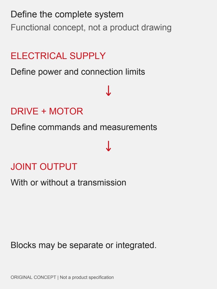
Why an electric architecture is attractive
A joint can be specified as connected functions
Instead of comparing only an actuator housing, write an interface map: incoming power, drive command, feedback, motor shaft, transmission and supported output. This makes the supplier boundary explicit. Integration can combine functions, but the buyer still needs to know which are included.
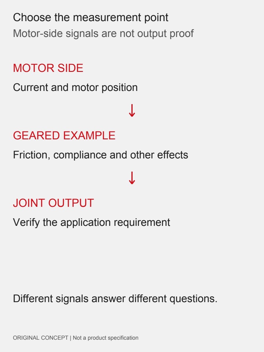
Control can be reviewed at the right measurement point
Motor current, motor position and joint-output behavior are different observations. MIT’s notes explain why transmission effects complicate the relationship between current and delivered joint torque. Request evidence at the point that matters to the application, rather than treating a motor-side signal as proof of output performance.
Transmission choices allow different joint compromises
Northwestern University’s Modern Robotics, Section 8.9, explains how gearing trades speed for torque and changes apparent rotor inertia. The robot-joint gearbox comparison gives related selection context. Specify the task first; a high ratio or a compact package alone does not qualify a joint.
Compare complete architectures, not slogans
The table is a review framework, not a ranking. Define the load cycle, envelope, available infrastructure and maintenance conditions before using it.
| Architecture | Include in the comparison | Ask for evidence of |
|---|---|---|
| Electric motor with transmission | Drive, feedback, gearing, support and cooling | Installed output behavior over the task cycle |
| Direct-drive electric joint | Motor envelope, current supply, support and cooling | Required output within electrical and thermal limits |
| Hydraulic joint | Actuator plus pressure supply, control, fluid circuit and support | Whole-system behavior and service requirements |
On a phone, swipe within the table to see all columns.
Do not infer efficiency, service life or runtime from the technology label. Ask for measurement boundaries and test conditions. Likewise, the absence of a gearbox does not remove the need to verify a motor, drive and installed output.
For an electric proposal, use the compact-joint heat-management checks to document the thermal conditions. Ask the supplier which conditions the stated limits assume and compare those assumptions with the installation.
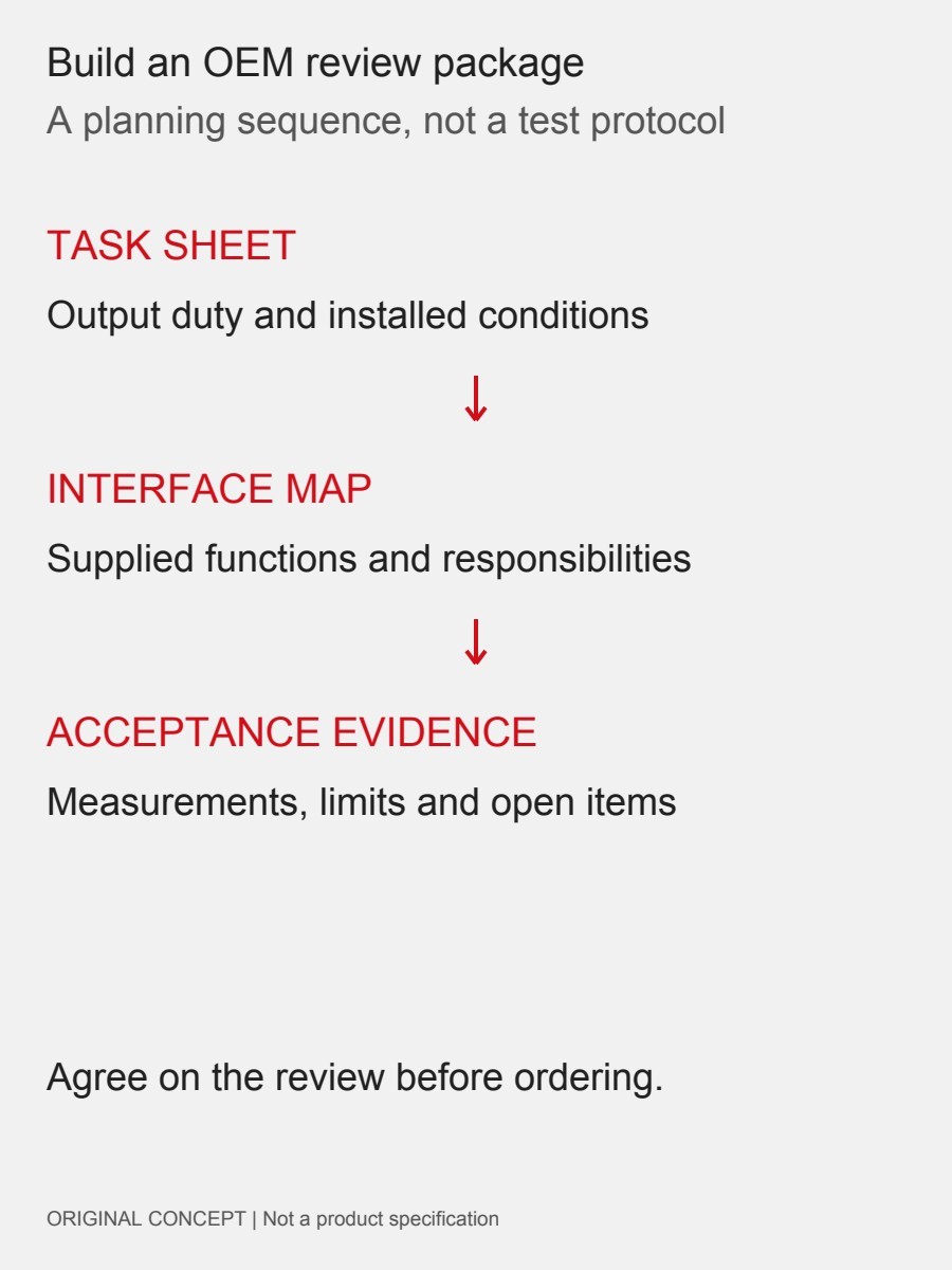
Turn interest into an OEM evaluation plan
- Define the task: name the output shaft and record torque, speed, motion range and duty together.
- Draw the supply boundary: assign the drive, sensors, transmission, output support, cables and heat path.
- Set acceptance conditions: decide what must be measured, under which load and installation conditions, and who accepts the result.
- Request comparable evidence: match every candidate to the same task and record unresolved assumptions before committing to a configuration.
The SolisMotor engineering-services overview is a starting point for discussing scope. Send the task sheet and interface map through the SolisMotor contact page. Ask for confirmation of the exact supplied configuration and available validation evidence; this article makes no delivery, certification or test-result promise.
Frequently asked questions
Does electric actuation mean direct drive?
No. An electric motor may drive the joint directly or through a transmission. Define the actual architecture.
Does motor current prove joint torque?
Not by itself. Transmission effects and measurement location matter; ask how output torque was established.
Are all humanoids moving away from hydraulics?
The cited notes describe a trend, not universal adoption. Select against the application and complete system evidence.
What should a buyer compare first?
The same task, installation boundary and acceptance conditions. Without those, specifications can describe different systems.
Technical context
Russ Tedrake, MIT, Robotic Manipulation, “Let’s get you a robot”; Kevin M. Lynch and Frank C. Park, Northwestern University, Modern Robotics, Section 8.9, “Actuation, Gearing, and Friction.” Web notes checked 4 November 2026; no precise page publication date is asserted. Review questions and diagrams are independently prepared. Neither institution endorses SolisMotor.