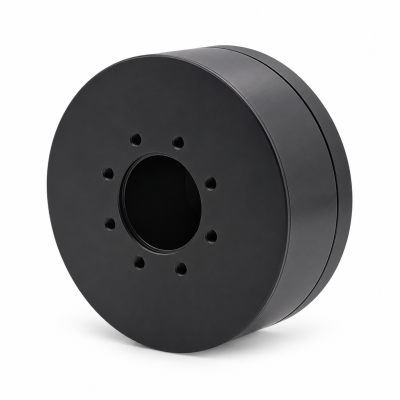
MG3505-8
 MG3505-9
 MG3505-36
 MG4315-8
 MG6010-6
 MG6010-8
 MG4305-10
 MG4310-10
 MG4310-36
 MG4310-40
 MG3510-8
 MG3510-64
 MG6010-36
 MG6010-48
 MG8108-6
 MG8108-8
 MG8108-36
 MG8108-48
 MG8115-6
 MG8115-9
 MG8115-36
 T-4024
 T-4929
 T-6034
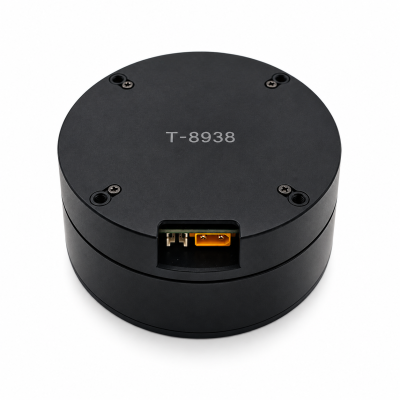
 T-8938
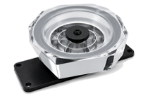
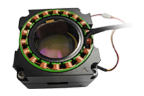
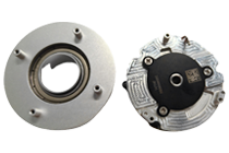
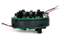
How to Design a Lightweight Humanoid Robot Actuator
Design a lightweight humanoid robot actuator by budgeting the complete installed joint and evaluating where its mass sits. Reduce or reposition mass only while preserving the required load capacity, stiffness, thermal performance, feedback and service access. Compare candidates on the same delivery boundary, then weigh and test the assembled joint. A lighter bare motor is not automatically a lighter or more capable robot limb.
Start with the SolisMotor Robot Joint Motor range to identify candidate architectures, then request an itemized installed-mass definition. This guide treats lightweight humanoid actuator design as a mass-allocation and verification problem, rather than a search for the smallest catalog weight.
Define the installed actuator mass before comparing designs
Write down what is included in each quoted weight. A motor-and-gearbox figure cannot be compared directly with an assembly that also includes output bearings, a drive, a brake and mounting hardware. Include the hardware needed by the actual installation, even when it is purchased separately.
Build a per-axis bill of mass with columns for component, quantity, measured or estimated mass, mounting location and owner of the missing evidence. Separate the actuator package from adjacent links, but keep both in the robot model. Avoid counting a shared housing, cable or support twice.
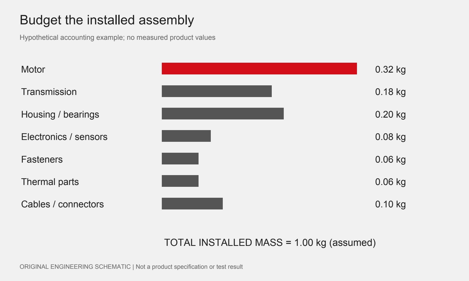
The following budget is entirely hypothetical. It illustrates accounting, not a SolisMotor product or a recommended allocation: motor 0.32 kg, transmission 0.18 kg, housing/support bearings 0.20 kg, electronics/sensors 0.08 kg, fasteners 0.06 kg, thermal parts 0.06 kg and local cables/connectors 0.10 kg. Total installed mass is 1.00 kg. Removing an item from the quote does not remove its mass from the robot.
Diagram: swipe horizontally on small screens.
Mass location matters as well as total kilograms
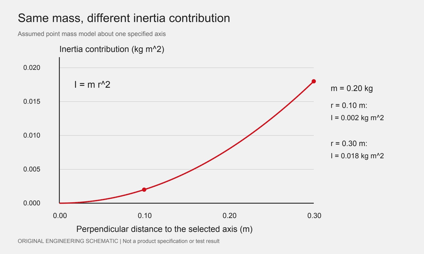
For rotation about a specified axis, a point-mass contribution to inertia is I = mr², where r is its perpendicular distance to that axis. A real component also has its own distributed inertia. Use its mass properties and the appropriate axis transformation rather than treating every part as a point. See OpenStax: calculating moments of inertia.
Hypothetical relocation example
Assume a 0.20 kg component is modeled as a point mass. At r = 0.30 m it contributes 0.018 kg·m² about the chosen axis; at r = 0.10 m it contributes 0.002 kg·m². The second contribution is one ninth of the first, although the component mass has not changed.
This example does not prove that moving a real drive closer to a hip is feasible or that total joint torque falls by the same factor. Check the added transmission, cable, mounting and cooling requirements, plus the changed loads on other joints. Recompute the complete robot model. For a horizontal lever under gravity, the separate moment-arm effect must also be modeled with its actual orientation.
Diagram: swipe horizontally on small screens.
Keep rotor inertia separate from limb mass
Gear ratio changes the rotor inertia seen at the output in a common simplified model: Ireflected = N²Irotor, with N defined as motor speed divided by output speed. MIT Drake documentation on reflected rotor inertia states the model and its approximation limits. Do not add this value as if it were kilograms of installed hardware, or treat it as the full limb inertia.
Evaluate each mass-saving change against the requirement it affects
Compare a proposed change with a documented baseline. Record the mass difference and the evidence needed to preserve each affected requirement. The table is a design-review checklist, not a prescription to use a particular material or transmission.
| Proposed change | Question to resolve | Evidence to retain |
|---|---|---|
| Reduce housing or support material | Are stress, deflection, fatigue and bearing alignment acceptable? | Load cases, analysis assumptions and corresponding physical checks |
| Combine mounts or interfaces | Does the assembly retain load paths, manufacturing access and serviceability? | Assembly drawing, tolerance review and installation trial |
| Move electronics or drive hardware | What changes in cable mass, routing, cooling and electrical interfaces? | Updated installed budget, drawings and system checks |
| Change motor or reduction | Can the new candidate meet the same paired torque–speed duty? | Confirmed operating limits and an equivalent duty test |
A smaller motor may require a different cooling arrangement; a revised housing may change the thermal path. Re-run the affected checks rather than infer performance from the weight difference. The robot joint thermal-management guide explains why the installed heat path belongs in that comparison.
Keep peak and continuous rating conditions explicit. Do not divide an unspecified peak torque by a bare-motor mass and compare the result with a continuous, fully installed assembly. Use the continuous-versus-peak torque guide when agreeing equivalent operating conditions.
Close the lightweight design with an installed measurement
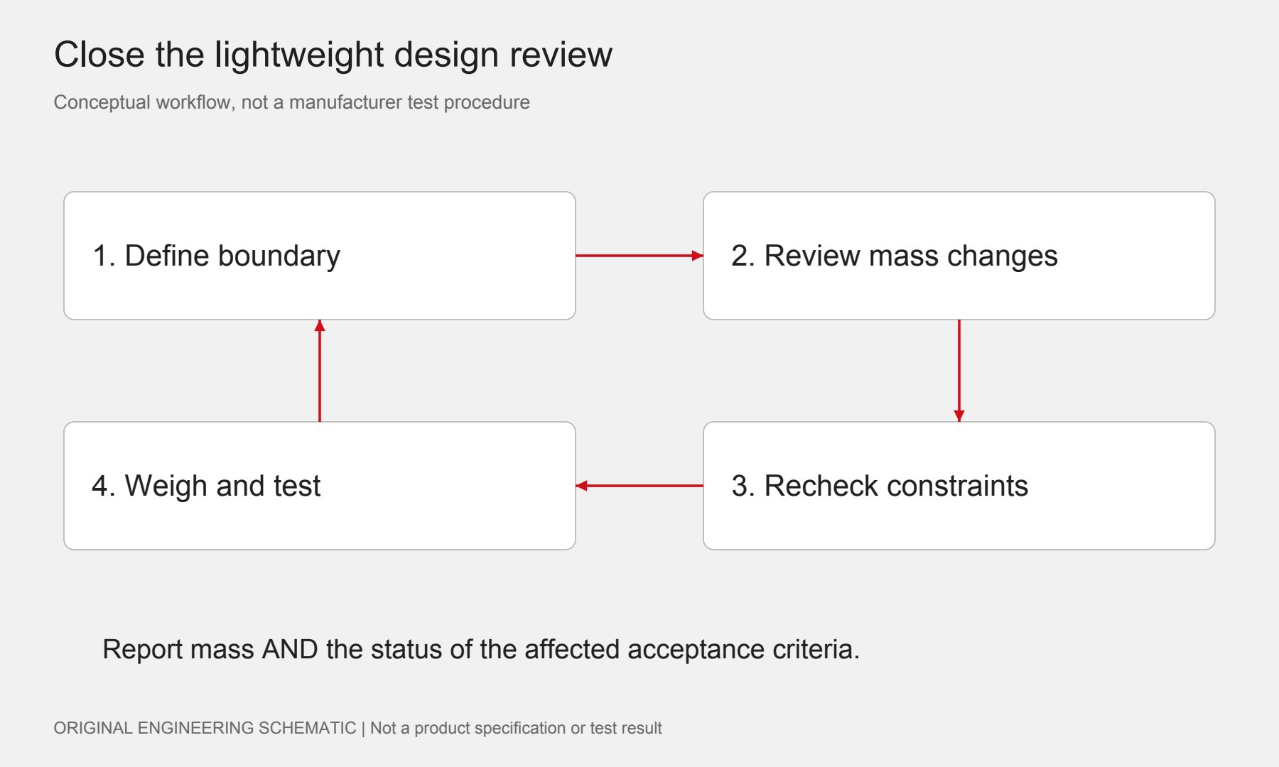
Freeze the bill of materials and assembly revision before reporting the result. Weigh the same defined boundary for the baseline and revised assembly, with comparable cables, fasteners, thermal parts and optional hardware. Record the instrument resolution and distinguish measured values from CAD estimates.
- Reconcile the budget. Explain differences between the estimated and measured mass; update the robot mass properties and component locations.
- Verify the changed constraints. Check the relevant structural, thermal, motion, cable-travel and feedback requirements under the agreed load cases.
- Report both outcomes. State the measured mass change and which functional acceptance criteria passed, failed or remain unverified. A successful weigh-in does not close an unfinished durability test.
Diagram: swipe horizontally on small screens.
The SolisMotor humanoid joint-drive solutions overview provides application context for discussing an architecture. For a scoped engineering inquiry, send the mass boundary, baseline budget, candidate changes, per-axis load history and acceptance criteria through the SolisMotor contact page. Ask for confirmed drawings and mass definitions; this article does not qualify a catalog model or promise a particular mass reduction.
Frequently asked questions
Is the lowest catalog weight always best?
No. First normalize the included hardware and operating requirements. Compare installed mass and mass distribution, then verify the relevant performance.
Does moving a component inward reduce its mass?
No. It can reduce that component’s inertia contribution about a selected axis. Other components and loads may change, so update the full model.
Can CAD mass replace a weigh-in?
Use CAD for budgeting with documented material and geometry assumptions. Confirm the completed assembly experimentally and reconcile the difference.
How much mass can be removed safely?
There is no universal percentage. The limit depends on the load cases, constraints, manufacturing process and evidence from the changed design.