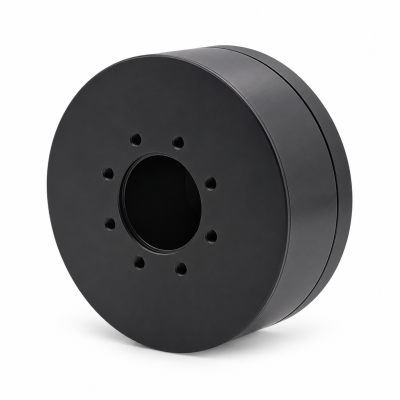
MG3505-8
 MG3505-9
 MG3505-36
 MG4315-8
 MG6010-6
 MG6010-8
 MG4305-10
 MG4310-10
 MG4310-36
 MG4310-40
 MG3510-8
 MG3510-64
 MG6010-36
 MG6010-48
 MG8108-6
 MG8108-8
 MG8108-36
 MG8108-48
 MG8115-6
 MG8115-9
 MG8115-36
 T-4024
 T-4929
 T-6034
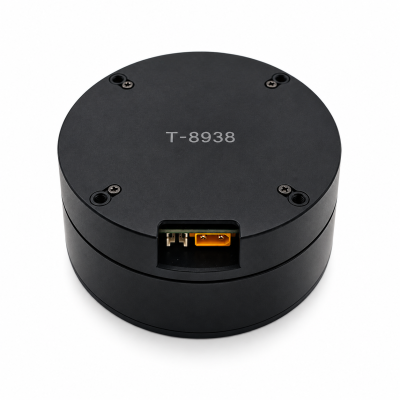
 T-8938
BLDC Motor vs PMSM: Choosing a Robot Joint Drive
Motor and drive matching · Robot joint engineering
Neither BLDC nor PMSM is automatically the better choice for a robot joint. Choose a motor-drive combination that meets the required motion, load and operating conditions. For slow movement and repeated reversals, the useful evidence is the motor's electrical characterization, the drive's supported configuration and the assembled joint's test results.
This guide explains how to compare those details. For the distinction between a motor type and a feedback-controlled motion system, see our BLDC versus servo guide.
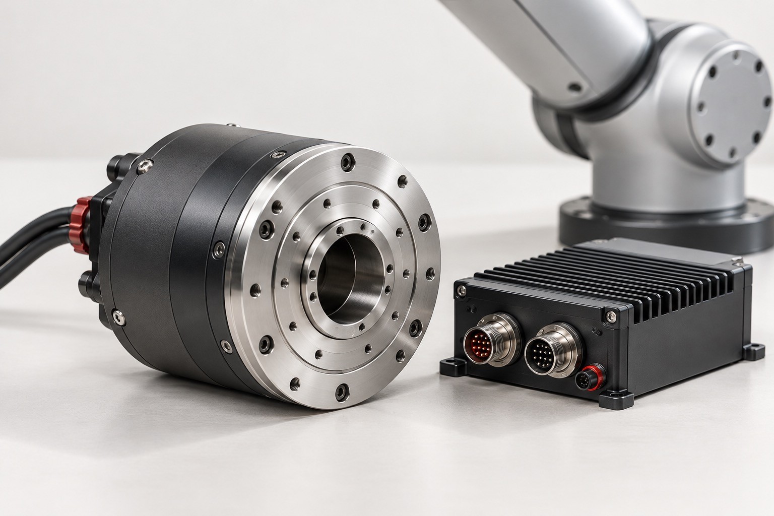
What do BLDC and PMSM mean in a specification?
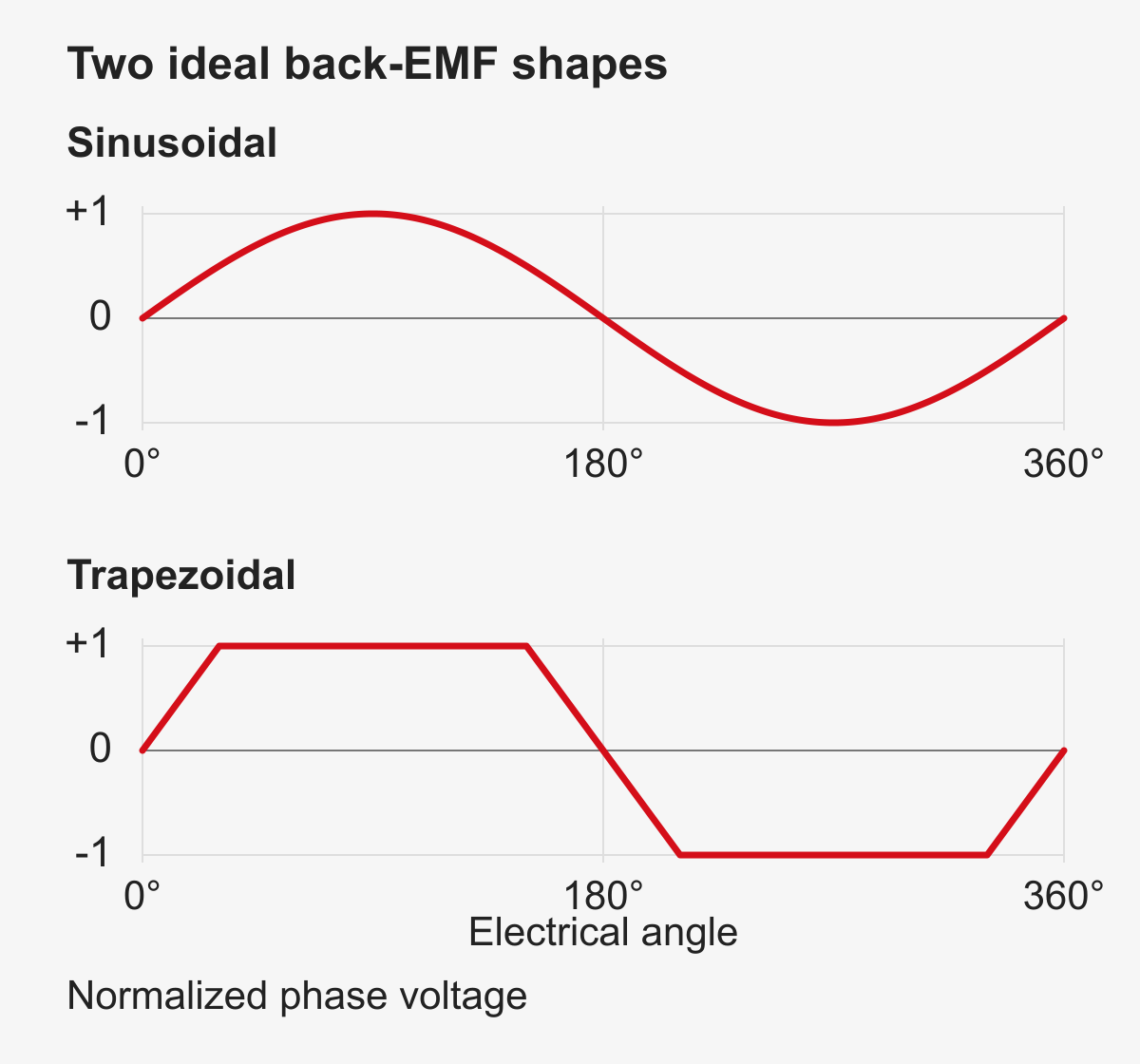
BLDC stands for brushless DC motor; PMSM stands for permanent magnet synchronous motor. Their use varies. Some technical sources describe BLDC within the wider permanent-magnet synchronous family. A narrower convention uses BLDC for approximately trapezoidal back electromotive force and PMSM for approximately sinusoidal back-EMF. Clarify which convention a supplier uses. [1, 2]
Back-EMF is the voltage induced as the rotor turns. The two idealized shapes below help explain the terminology; they do not identify the waveform of a particular product.
Keep three questions separate when reading a specification:
On narrow screens, swipe across the table to see all columns.
| Question | What to establish |
|---|---|
| What is the motor's back-EMF waveform? | Request the characterization, test speed and whether the voltage is measured phase-to-neutral or line-to-line. |
| What current does the drive produce? | Confirm the intended phase-current waveform and the conditions under which it is controlled. |
| What can the assembled joint do? | Request results at the required output load, speed, temperature and mechanical configuration. |
A photograph, supply-voltage label or encoder specification cannot settle the waveform question. Record it as unconfirmed if the necessary motor data are unavailable.
Six-step, sinusoidal control and FOC describe the drive
Six-step commutation progresses through six switching sectors per electrical cycle. Sinusoidal commutation targets approximately sinusoidal phase currents. Field-oriented control (FOC) regulates current components in a reference frame aligned with rotor flux, using a measured or estimated rotor angle. Sinusoidal control and FOC are therefore not interchangeable names for the same implementation. [2, 3, 5]
FOC can be used with suitable motors described as BLDC, while documented six-step implementations also support PMSM. These examples show why neither label assigns one compulsory control method; they do not prove that an arbitrary motor and drive are compatible. [3, 4]
For the proposed pairing, confirm:
- The exact motor, drive hardware, firmware and feedback configuration.
- The supported control modes and motor parameters the drive requires.
- The DC-bus range and current limits, including whether current values are peak or RMS.
- The operating range demonstrated with that configuration.
Matching the intended current waveform to the motor's characteristics is part of drive selection. The compatible supply and current range also need checking. [3] Treat a controller's “BLDC/PMSM” label as a prompt for these questions, rather than as a completed compatibility assessment.
Why low-speed movement needs separate evidence
Steady operation at a higher speed does not establish how a joint will start under load, creep or reverse direction. In conventional sensorless methods that detect back-EMF zero crossings, the available signal falls with speed, so startup needs a suitable strategy. This limitation applies to the method described; it must not be extended to every sensorless algorithm. [6]
Ask for the selected drive's demonstrated startup behavior and lowest usable speed with the actual motor. With a sensored drive, confirm the feedback interface and angle alignment. An encoder's presence alone does not establish that the combination has been tuned or tested.
Motor-angle feedback supports drive operation; it does not, by itself, establish output-shaft positioning accuracy. Evaluate the assembled joint at the output as well as the motor side.
Also separate torque ripple from motion tracking. Specify the ripple measure—such as peak-to-peak variation—and the measurement location. Record tracking error independently. Neither a low ripple claim nor a control-method name replaces a joint-level motion test.
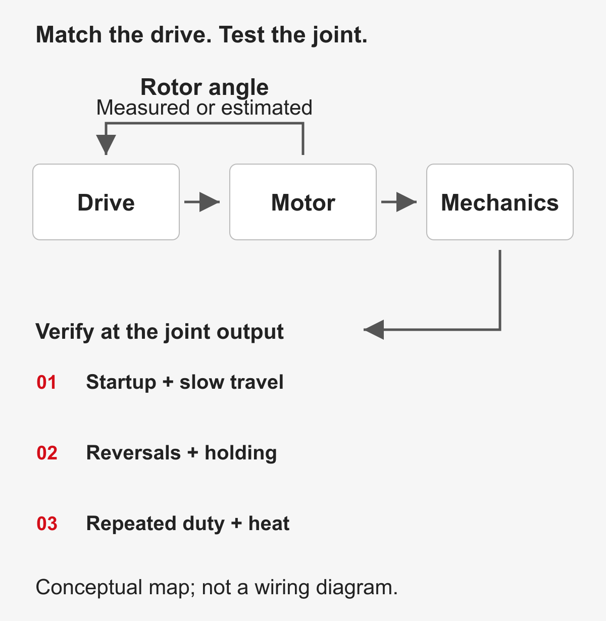
A 0.5 rpm joint requirement: what should you test?
Consider an illustrative calculation, not a SolisMotor test result. Suppose a joint must move at 0.5 rpm at its output through a 9:1 reduction. Here, reduction ratio means motor mechanical speed divided by output speed.
Motor mechanical speed = output speed × reduction ratio
0.5 rpm × 9 = 4.5 rpm
This establishes a speed to evaluate. It does not establish available torque, efficiency, startup capability or positioning accuracy. Test each candidate motor-drive combination at the required output load and the corresponding motor operating point.
The following plan is an engineering starting point. Set acceptance limits for the application before testing; no results are claimed here.
On narrow screens, swipe across the table to see all columns.
| Test | Keep comparable | Record |
|---|---|---|
| Loaded startup and slow travel | Output load, supply, motion profile and initial temperature | Startup success, tracking error, current and speed variation |
| Direction reversal | Reversal profile, load and transmission configuration | Transient motion error, current peaks and settling behavior |
| Holding and repeated duty | Holding torque, duty cycle, cooling and temperature limits | Temperature rise, holding behavior and protection events |
| Noise and torque variation | Measurement location, bandwidth, load and speed | Measured values, units and the method used for each measurement |
Use the same mechanics when isolating the effect of a motor-drive change. When comparing complete actuator packages, document their mechanical differences. Our torque, heat and integration guide covers the wider joint requirements.
Applying the comparison to a SolisMotor joint motor
The MG8108-9 listing reviewed on October 9, 2026 describes an integrated BLDC servo motor with a 9:1 planetary gearbox, drive electronics and 14-bit encoder resolution. It also lists support for secondary output-shaft encoder feedback. Confirm the supplied configuration rather than assuming that every supported option is included.
Those are integration details. They do not establish the motor's back-EMF waveform or exact current-control implementation. The 0.5 rpm calculation above is hypothetical; it is not validation of MG8108-9 at that operating point.
SolisMotor's published engineering services include motor, gearbox and drive matching recommendations, plus prototype validation support. A useful specification combines the intended output motion, load and duty cycle with the waveform, compatibility or test evidence needed for selection.
Product and service information checked on October 9, 2026. This article presents no comparative product test.
Frequently asked questions
Can a BLDC motor use FOC?
Yes, when the specified motor and drive support that configuration. Confirm the compatible pairing and its validated operating range. [3]
Does a PMSM always require FOC?
No. Official technical documentation also describes sinusoidal-control and six-step implementations. Compatibility and suitability still need checking for the selected motor and robotic task. [2, 4]
Does an encoder identify the motor as PMSM rather than BLDC?
No. Feedback hardware and the motor's induced-voltage waveform describe different aspects of the assembly. Request the electrical characterization and drive configuration.
What if the supplier does not publish a back-EMF waveform?
Request its recommended motor-drive pairing, compatibility documentation and application test conditions. Leave the waveform classification unconfirmed until supporting information is available.
Technical references
The following sources support the technical principles. They do not indicate a partnership with SolisMotor or measured performance of its products.
- Microchip, Brushless DC (BLDC) Motor Controllers and Drivers; undated page, reviewed October 9, 2026.
- Microchip, AN1017 / DS01017A, Sinusoidal Control of PMSM Motors with dsPIC30F DSC; December 2005.
- Texas Instruments, SLVAES1A, Brushless-DC Motor Driver Considerations and Selection Guide; revised May 2022.
- STMicroelectronics, STM32MotorControl:6-step Firmware Algorithm; page date unconfirmed, reviewed October 9, 2026.
- Microchip, AN2757 / DS00002757A, Sensored (Encoder-Based) Field Oriented Control of Three-Phase Permanent Magnet Synchronous Motor (PMSM); 2018.
- Microchip, AN885 / DS00885A, Brushless DC (BLDC) Motor Fundamentals; 2003.