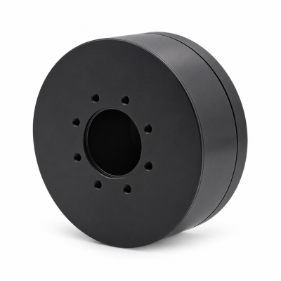
MG3505-8
 MG3505-9
 MG3505-36
 MG4315-8
 MG6010-6
 MG6010-8
 MG4305-10
 MG4310-10
 MG4310-36
 MG4310-40
 MG3510-8
 MG3510-64
 MG6010-36
 MG6010-48
 MG8108-6
 MG8108-8
 MG8108-36
 MG8108-48
 MG8115-6
 MG8115-9
 MG8115-36
 T-4024
 T-4929
 T-6034
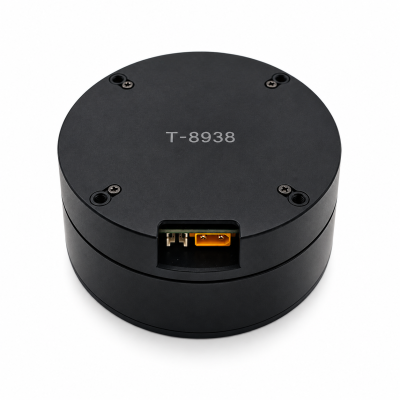
 T-8938
How Quadruped Joint Motors Drive a Stride
Quadruped joint motors apply torque at the hip and knee. During stance, that torque helps support and move the body through the feet on the ground. During swing, it lifts and places the foot. A controller that responds to contact uses its estimate of touchdown to decide when to change the leg’s task.
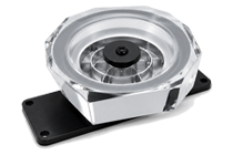
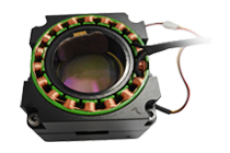
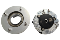
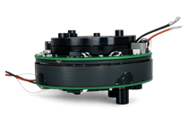
The SolisMotor robot joint motor range provides examples of joint-drive packages. The walkthrough follows one leg from stance to the next touchdown, then shows what to log if the foot lands at the wrong time.
What the hip and knee axes do
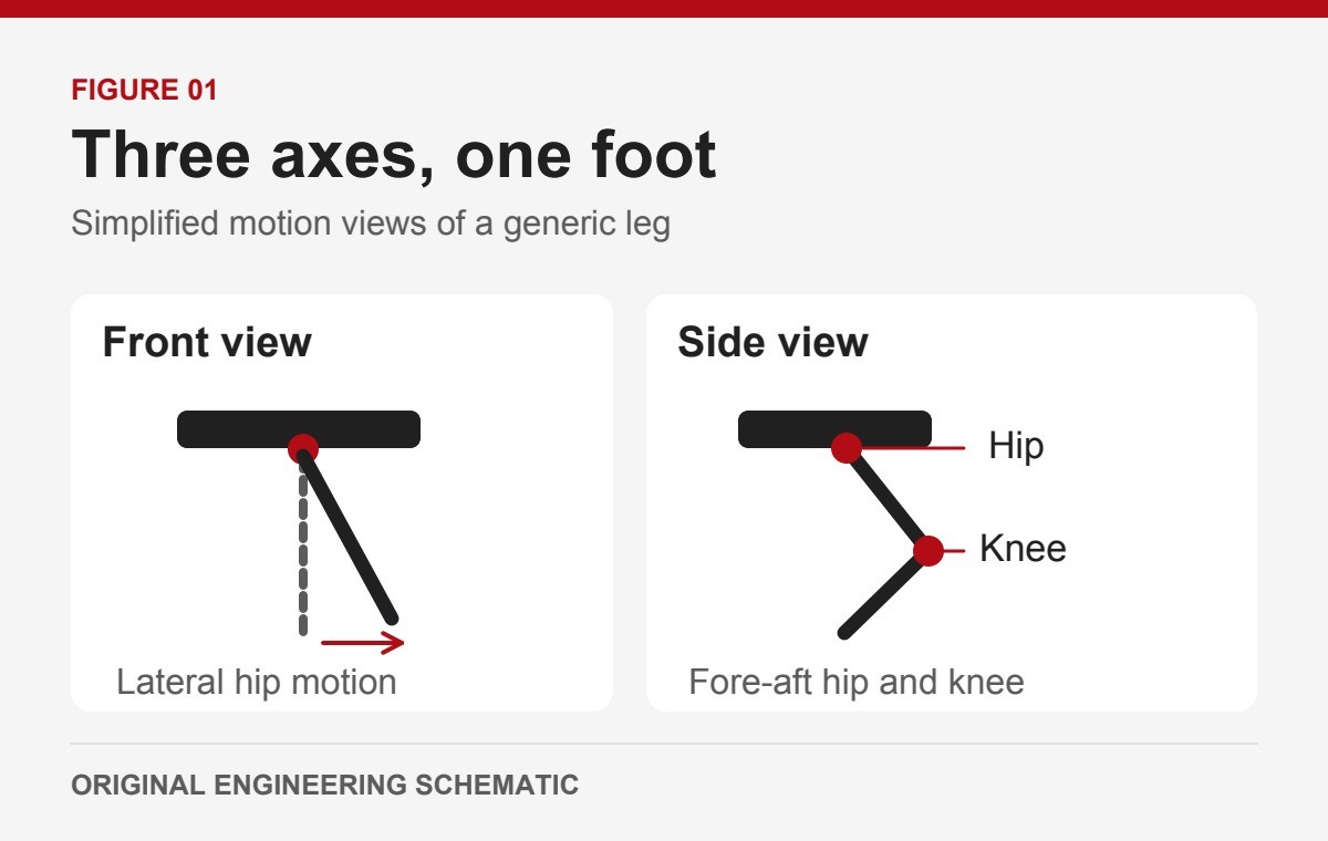
One common three-axis leg uses a lateral hip axis, a fore-aft hip axis and a knee axis. The lateral axis can move the leg toward or away from the body, which helps set stance width and make sideways corrections. The fore-aft hip axis and knee work together to position the foot in the front-to-back plane and change how far it reaches. Which axis moves most depends on the geometry and the target foot path.
A foot target can require several axes at once. Likewise, a force under one foot can load several joints. The mechanical output of a joint may be at a different physical location from its motor if a linkage transmits the motion. Read the axis drawing and the supplied interface before assuming the motor is located directly at the pivot.
How the job changes through one stride
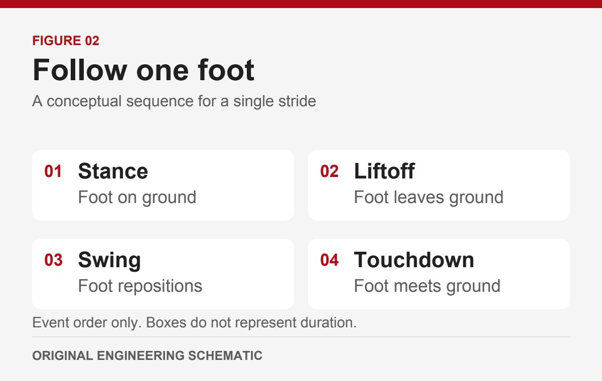
During stance, the foot is in contact with the ground. The controller distributes support and propulsion across the legs that are in contact. Joint torques help the leg transmit those forces while the body moves. The force borne by a foot changes as the body moves and other feet enter or leave support.
During swing, the foot is off the ground and is repositioned. Hip and knee motion shape foot clearance, landing position and approach speed. The leg still needs torque to move its own mass. When comparing traces, look at the point in the stride as well as the motor signal.
For component sizing from these demands, see the separate quadruped motor selection guide, which covers torque, duty cycle and component qualification.
What changes when the foot lands
Touchdown can trigger a change from swing tracking to a support strategy. The gait plan predicts when the foot should land. The contact estimator reports when it thinks the foot has landed. A controller can use both signals to handle early or late contact, as shown in the MIT study on contact detection and event-based gait control (external source). The exact response depends on the control design.
Example: The foot meets an unexpected raised surface
Suppose the plan still calls for the foot to move downward, but contact occurs earlier. If the contact estimate changes promptly, a controller designed to react to that event can start its support response. If the estimate stays in swing, the commanded path may keep pressing into the surface until the controller reacts. A rise in current can accompany contact, acceleration or a change in friction. Use the contact and motion records to interpret it.
Example: The expected foothold is lower
The gait plan may mark the start of stance while the foot is still in the air. Compare the planned stance flag with independent contact evidence, such as the normal force crossing a documented threshold on a force plate. A threshold crossing gives a repeatable time reference. How much support the leg provides is a separate force measurement. Then check how the controller is configured to handle a missing contact and whether the contact flag follows the actual event.
Compare independent contact evidence, the controller’s contact flag, the command it sent and the command the drive applied. Then compare measured motion with the applied command. If the drive does not expose when it applied the command, the log cannot separate time spent in transit or buffering from the drive’s response.
How to read a touchdown trace
Record the same event on a common time base across the gait controller and the drive. If the devices have separate clocks, align them or report the timing uncertainty. Start with the signals below and record which values are measured, commanded or estimated.
Swipe within the table to see all columns.
| Signal group | Record | What it helps separate |
|---|---|---|
| Gait and contact | Planned phase, estimated contact, and an independent contact timestamp if available (s). | Expected timing versus observed contact and controller recognition. |
| Joint command and motion | Controller send time and, if available, drive apply time. Log commanded and measured position or speed (rad or rad/s) per axis. | Delay before the drive applies the command versus tracking error after it applies it. |
| Drive effort and limits | Current (A, with convention), torque command or estimate (N·m, identify motor or output side), and active drive limit flags, such as a current or thermal limit if reported. | An effort request versus an electrical limit. Direct output-torque measurement, if needed, is a separate channel. |
Signal units are examples for a test record. If a device reports other units, document the conversion and sign convention.
Worked example: locate the longest interval
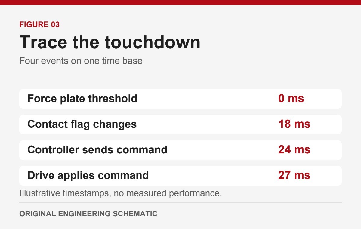
Assume a test rig uses the force plate’s threshold crossing as time zero and the clock alignment and sampling together leave up to ±2 ms uncertainty in each interval. In this illustrative log, the contact flag changes at 18 ms, the controller sends the new command at 24 ms and the drive applies it at 27 ms.
The three gaps are 18 ms to the flag, 6 ms from the flag to send, and 3 ms from send to apply. The first gap stays the longest even allowing for the stated uncertainty, so review the contact signal and estimator first. Check the measured joint response after the command is applied. These numbers are assumptions for this example and supply no pass limit.
The SolisMotor MG8108-9 knee joint actuator listing is a catalog example of an integrated drive package. To discuss an OEM application with SolisMotor engineering services, share the leg axis drawing, planned gait events, a short trace and the available feedback channels through the SolisMotor contact page. Ask which data the proposed configuration actually exposes.
Frequently asked questions
Do the motors keep producing torque when a foot is in the air?
Yes. They move the leg links along the planned path and may slow the foot before touchdown. A loss of ground contact changes the loading task but leaves the leg’s inertia and weight.
Does the knee motor control foot height by itself?
In the three-axis example, foot height depends on the combined leg pose. A knee motion can change reach and height, while the hip axes can help place the foot and steer the leg.
Does motor current tell me when the foot touched down?
Current is one clue. Match it with the phase, motion and contact evidence. Its meaning depends on the drive, the command and the drivetrain.
Technical basis: Gerardo Bledt et al., MIT Cheetah 3: Design and Control of a Robust, Dynamic Quadruped Robot, IROS 2018, DOI 10.1109/IROS.2018.8593885. Gerardo Bledt et al., Contact Model Fusion for Event-Based Locomotion in Unstructured Terrains, ICRA 2018, DOI 10.1109/ICRA.2018.8460904. Jared Di Carlo et al., Dynamic Locomotion in the MIT Cheetah 3 Through Convex Model-Predictive Control, IROS 2018, DOI 10.1109/IROS.2018.8594448. Illustrations and the test checklist are original explanations.